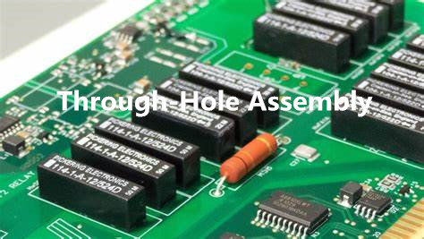
Through-hole PCB boards have been a staple in the electronics industry for decades. These boards are designed to accommodate electronic components with wire leads that can be inserted into pre-drilled holes on the board and then soldered into place. This design provides a reliable connection between the component and the board, making it a popular choice for many applications.
One of the benefits of through-hole PCB boards is their durability. The soldered connections provide a strong hold, making them resistant to vibration and shock. This makes them ideal for applications where the board may be subjected to harsh environments, such as in automotive or aerospace industries. Additionally, through-hole components are generally easier to replace than surface-mount components, which can be a significant advantage in certain situations.
Overall, through-hole PCB boards remain a popular choice for many electronic applications due to their reliability and durability. While surface-mount technology has become increasingly popular in recent years, through-hole boards continue to have a place in the industry and are often preferred for certain applications.
What is a Through Hole PCB Board?
Definition
A through hole PCB board is a type of printed circuit board that has components inserted into drilled holes and soldered onto copper pads on the opposite side of the board. This method of construction is in contrast to surface-mount technology (SMT) where the components are mounted directly onto the surface of the board.
Benefits
Through hole PCB boards have several benefits over SMT boards, including:
-
Durability: Through hole components are mechanically secured to the board, making them less likely to break or become dislodged during use.
-
Ease of repair: Through hole components can be easily replaced or repaired with basic tools and skills.
-
Better for high current applications: Through hole components have larger solder joints, making them better suited for high current applications.
-
Better for prototyping: Through hole components are easier to work with for prototyping and experimentation, as they can be easily inserted and removed from the board.
In summary, through hole PCB boards offer a reliable and durable construction method for electronic circuits, particularly for high current applications and prototyping purposes.
Types of Through Hole PCB Boards
When it comes to through hole PCB boards, there are three main types: single-sided, double-sided, and multilayer. Each type has its own advantages and disadvantages, and choosing the right one for your project is essential.

Single-Sided Through Hole PCB Boards
Single-sided through hole PCB boards are the simplest and most common type of through hole PCB board. They have components and traces on only one side of the board, with holes drilled through the board to allow for through hole components to be inserted and soldered in place.
Single-sided through hole PCB boards are generally less expensive than other types of through hole PCB boards, making them a great option for simple projects or prototypes. However, they are limited in terms of complexity and functionality.
Double-Sided Through Hole PCB Boards
Double-sided through hole PCB boards have components and traces on both sides of the board, connected by through holes. This allows for more complex circuits and greater functionality than single-sided through hole PCB boards.
Double-sided through hole PCB boards are more expensive than single-sided through hole PCB boards, but they are still relatively affordable. They are a good option for more complex projects that require greater functionality.
Multilayer Through Hole PCB Boards
Multilayer through hole PCB boards have multiple layers of components and traces, connected by through holes. This allows for even greater complexity and functionality than double-sided through hole PCB boards.
Multilayer through hole PCB boards are the most expensive type of through hole PCB board, but they are also the most versatile. They are a good option for complex projects that require a high level of functionality and reliability.
In summary, the type of through hole PCB board you choose will depend on the complexity and functionality of your project, as well as your budget. Single-sided through hole PCB boards are the simplest and most affordable, while multilayer through hole PCB boards are the most complex and expensive. Double-sided through hole PCB boards offer a good balance between cost and functionality.
Designing a Through Hole PCB Board
Schematic Design
The first step in designing a through hole PCB board is to create a schematic design. This involves drawing a diagram of the circuit that you want to create, including all of the components and their connections. There are many software programs available that can help you create a schematic design, such as Eagle, KiCad, and Altium.
Component Placement
Once you have created a schematic design, the next step is to place the components on the board. This involves deciding where each component will go and how it will be oriented. It is important to ensure that there is enough space between components to allow for proper soldering and assembly.
Routing
After the components have been placed, the next step is to route the connections between them. This involves creating copper traces on the board to connect the pins of each component. It is important to ensure that the traces are the correct width and spacing, and that they do not cross over each other.
Drilling
The final step in designing a through hole PCB board is to drill the holes for the components. This involves creating holes in the board where each component will be placed. It is important to ensure that the holes are the correct size and spacing, and that they are located in the correct positions.
In conclusion, designing a through hole PCB board requires careful planning and attention to detail. By following the steps outlined above, you can create a high-quality board that will function reliably and efficiently.
Manufacturing Through Hole PCB Boards
Printed Circuit Board (PCB) Fabrication
Through hole PCB boards are manufactured using a multi-step process that involves various stages. The first step in manufacturing a through hole PCB board is to create a design for the circuit board using computer-aided design (CAD) software. The design is then converted into a Gerber file, which is used to create a photomask.
The photomask is used to create a negative image of the circuit board design on a copper-clad board. The board is then etched using a chemical process to remove the copper from the areas not covered by the photomask. After etching, the board is cleaned to remove any remaining chemicals and the photomask is removed.
The next step is to drill holes in the board for the through-hole components. This is done using a drilling machine that is programmed to drill holes at specific locations and sizes. The board is then plated with a thin layer of copper to ensure good electrical conductivity.

Component Assembly
Once the PCB board has been fabricated, the next step is to assemble the components. Through-hole components are inserted into the drilled holes on the board and then soldered in place. This is typically done using a wave soldering machine, which applies a wave of molten solder to the bottom of the board, allowing the solder to flow into the holes and create a solid electrical connection.
Quality Control
Quality control is an important part of the manufacturing process for through hole PCB boards. After assembly, the board is inspected to ensure that all components are properly placed and soldered. This is done using automated optical inspection (AOI) machines that can quickly scan the board for defects.
In addition to AOI, other quality control measures may include functional testing to ensure that the board is working properly, as well as environmental testing to ensure that the board can withstand various conditions such as temperature and humidity.
Overall, through hole PCB board manufacturing is a complex process that requires careful attention to detail and quality control at every step. By following these steps and using the right equipment and techniques, it is possible to create high-quality through hole PCB boards that meet the needs of a wide range of applications.
Applications of Through Hole PCB Boards
Through hole PCB boards are widely used in various industries due to their durability and reliability. They are commonly used in applications where components need to be securely mounted and where the board may be exposed to harsh environments. Below are some of the most common applications of through hole PCB boards.
Consumer Electronics
Through hole PCB boards are commonly used in consumer electronics such as televisions, radios, and computers. These boards are used to mount various components such as resistors, capacitors, and diodes. The through hole design allows for a secure connection between the component and the board, ensuring reliable performance.
Industrial Equipment
Through hole PCB boards are also used in industrial equipment such as control systems, power supplies, and sensors. These boards are designed to withstand harsh environments such as extreme temperatures and vibrations. The through hole design allows for a secure connection between the component and the board, ensuring reliable performance in these demanding applications.
Medical Devices
Through hole PCB boards are also used in medical devices such as pacemakers, defibrillators, and diagnostic equipment. These boards are designed to meet strict regulatory requirements and must be highly reliable. The through hole design allows for a secure connection between the component and the board, ensuring reliable performance in these critical applications.
Overall, through hole PCB boards are widely used in various industries due to their durability and reliability. They are an essential component in many electronic devices and play a critical role in ensuring reliable performance.
Comments are closed