Rigid and flex PCBs are two types of printed circuit boards that are commonly used in electronic devices. The main difference between the two is their flexibility. Rigid PCBs are made from a solid substrate material and cannot be bent or twisted, whereas flex PCBs are made from a flexible substrate material that allows them to be bent and twisted to fit into tight spaces.
Rigid PCBs are typically used in applications where durability and stability are important, such as in automotive, aerospace, and military applications. They are also used in consumer electronics, such as computers and smartphones. Flex PCBs, on the other hand, are used in applications where flexibility and space-saving are important, such as in medical devices and wearable technology.
Both types of PCBs have their own advantages and disadvantages, and choosing the right type for a specific application depends on a variety of factors, including the device’s size, shape, and intended use. In this article, we will explore the differences between rigid and flex PCBs, their applications, and the factors to consider when choosing between the two.
What are Rigid and Flex PCBs?
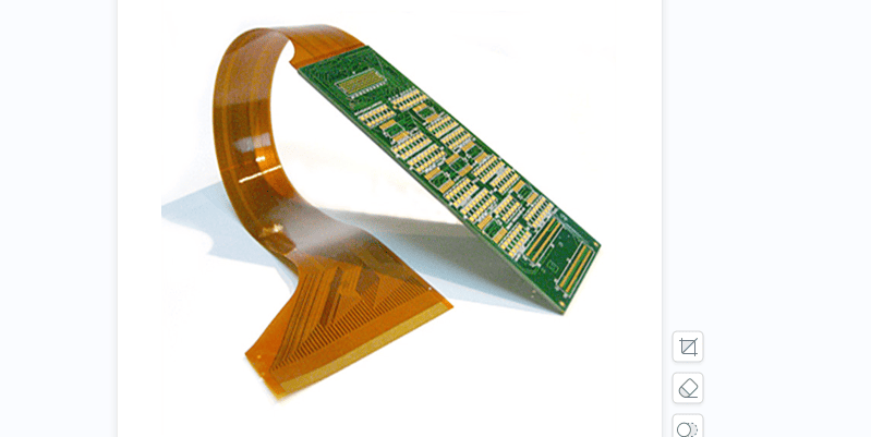
Printed Circuit Boards (PCBs) are an essential component of many electronic devices. They allow for the connection of electronic components and provide a surface for mounting. There are two main types of PCBs: rigid and flex.
Rigid PCBs are made of a solid substrate material, such as fiberglass or plastic, and are designed to be inflexible. They are commonly used in devices that require a stable and secure mounting surface, such as desktop computers, televisions, and other consumer electronics.
Flex PCBs, on the other hand, are designed to be flexible. They are made of a thin, flexible substrate material, such as polyimide, and are ideal for use in devices that require a flexible or curved mounting surface, such as wearable technology, medical devices, and automotive applications.
Flex PCBs are more versatile than rigid PCBs, as they can be bent, folded, and twisted to fit into tight spaces or conform to irregular shapes. They also offer improved durability and reliability, as they are less likely to break or crack under stress.
In summary, rigid PCBs are designed for applications that require a stable and secure mounting surface, while flex PCBs are designed for applications that require a flexible or curved mounting surface. Both types of PCBs are essential components of many electronic devices and play a critical role in the functioning of modern technology.
Advantages of Rigid PCBs
High Durability
Rigid PCBs are more durable than their flexible counterparts due to their solid construction. They are less prone to damage from bending or twisting, making them ideal for applications that require high reliability and longevity. Rigid PCBs are also less likely to suffer from warping or deformation, which can affect the performance of the circuit.
Cost-Effective
Rigid PCBs are generally less expensive to manufacture than flexible PCBs, making them a cost-effective choice for many applications. They are also easier to assemble, reducing labor costs and increasing efficiency. In addition, rigid PCBs can be produced in large quantities, reducing the overall cost per unit.
Easy to Design and Manufacture
Rigid PCBs are easier to design and manufacture than flexible PCBs, as they do not require the same level of precision and attention to detail. They can be produced using standard manufacturing techniques, such as drilling and etching, which are well-established and widely used in the industry. Rigid PCBs are also easier to test and troubleshoot, as they can be easily accessed and inspected.
Overall, the advantages of rigid PCBs make them a popular choice for a wide range of applications. Their high durability, cost-effectiveness, and ease of design and manufacture make them a reliable and practical solution for many circuit board needs.
Advantages of Flex PCBs
Bendable and Foldable
Flex PCBs are designed to be flexible and can be bent or folded to fit into tight spaces. This makes them ideal for applications where space is limited, and traditional rigid PCBs are not feasible. Flex PCBs can also be bent to fit around corners or other obstacles, which can help reduce the overall size of the device.
Lightweight
Flex PCBs are much lighter than traditional rigid PCBs, which makes them ideal for applications where weight is a concern. The reduced weight of flex PCBs can help reduce the overall weight of the device, which can be especially important in applications such as aerospace or automotive industries.
Compact Design
Flex PCBs can be designed to fit into very compact spaces, which can help reduce the overall size of the device. This is especially important in applications where space is at a premium, such as in medical devices or consumer electronics.
Overall, flex PCBs offer many advantages over traditional rigid PCBs. They are lightweight, compact, and can be bent or folded to fit into tight spaces. This makes them ideal for a wide range of applications where traditional rigid PCBs are not feasible.
Applications of Rigid and Flex PCBs
Rigid and flex PCBs are widely used in various industries due to their unique properties. Here are some of the applications of rigid and flex PCBs:
Consumer Electronics
Consumer electronics are the most common application of rigid and flex PCBs. These PCBs are used in smartphones, laptops, tablets, cameras, and other electronic devices. Rigid PCBs are used in the main circuit board of the device, while flex PCBs are used in the flexible parts of the device, such as the screen and the keypad. The use of flex PCBs in these devices allows them to be thinner, lighter, and more flexible.
Medical Devices
Rigid and flex PCBs are also used in medical devices, such as pacemakers, defibrillators, and insulin pumps. These devices require high reliability and precision, and rigid and flex PCBs can provide that. Rigid PCBs are used in the main circuit board of the device, while flex PCBs are used in the flexible parts of the device, such as the electrodes. The use of flex PCBs in these devices allows them to be more comfortable and less invasive.
Automotive Industry
Rigid and flex PCBs are also used in the automotive industry, particularly in the dashboard, infotainment system, and engine control unit. These PCBs are used to control the various functions of the vehicle, such as the speedometer, odometer, and fuel gauge. Rigid PCBs are used in the main circuit board of the device, while flex PCBs are used in the flexible parts of the device, such as the steering wheel and the dashboard. The use of flex PCBs in these devices allows them to be more comfortable and less invasive.
Overall, rigid and flex PCBs are essential components in various industries, and their unique properties make them ideal for various applications.
Design Considerations for Rigid and Flex PCBs
When designing a printed circuit board (PCB), there are several considerations that must be taken into account to ensure the final product meets the desired specifications. This is especially important when designing rigid and flex PCBs, which require different design considerations due to their unique characteristics. Here are some key design considerations to keep in mind when designing a rigid or flex PCB.
Material Selection
The choice of materials is critical when designing a rigid or flex PCB. For rigid PCBs, materials such as FR-4 and CEM-1 are commonly used due to their low cost and high durability. Flex PCBs, on the other hand, require materials that are flexible and can withstand repeated bending without cracking or breaking. Materials such as polyimide and polyester are commonly used for flex PCBs due to their flexibility and high-temperature resistance.
Trace Width and Spacing
The trace width and spacing of a PCB are important considerations that affect the performance and reliability of the final product. When designing a rigid PCB, the trace width and spacing can be relatively large due to the board’s rigidity. However, when designing a flex PCB, the trace width and spacing must be smaller to accommodate the board’s flexibility. This is because smaller traces and spacing reduce the stress on the board when it is bent.
Bend Radius
The bend radius is the minimum radius that a flex PCB can be bent without damaging the board’s components or traces. When designing a flex PCB, it is important to choose a bend radius that is appropriate for the board’s intended use. A larger bend radius will reduce the stress on the board when it is bent, but it will also increase the board’s size and weight. Therefore, it is important to strike a balance between the board’s flexibility and its size and weight.
In conclusion, designing a rigid or flex PCB requires careful consideration of several factors, including material selection, trace width and spacing, and bend radius. By taking these factors into account, you can ensure that your final product meets the desired specifications and performs reliably.
Manufacturing Process for Rigid and Flex PCBs
Drilling and Plating
The first step in the manufacturing process for both rigid and flex PCBs is drilling and plating. Holes are drilled in the substrate material, and then the holes are plated with copper to create electrical connections between the layers of the board. This process requires precision machinery and a skilled operator to ensure that the holes are drilled and plated accurately.

Etching and Lamination
After drilling and plating, the board is coated with a layer of photoresist material. The photoresist is then exposed to ultraviolet light through a mask, which creates a pattern on the board. The board is then etched in a solution that removes the copper from the areas that were not protected by the photoresist. This process is repeated for each layer of the board.
Once all of the layers have been etched, they are laminated together under heat and pressure to create a single board. This process requires precision equipment and careful handling to ensure that the layers are aligned correctly.
Assembly and Testing
After lamination, the board is ready for assembly. Components are placed on the board using automated equipment, and then the board is soldered to create electrical connections between the components and the board. This process requires skill and precision to ensure that the components are placed and soldered correctly.
Finally, the board is tested to ensure that it functions as intended. This testing includes both electrical and functional testing to ensure that the board is reliable and meets all of the required specifications.
In conclusion, the manufacturing process for rigid and flex PCBs requires precision machinery, skilled operators, and careful handling. The process includes drilling and plating, etching and lamination, and assembly and testing. Each step is critical to ensuring that the final product is reliable and meets all of the required specifications.
Comments are closed