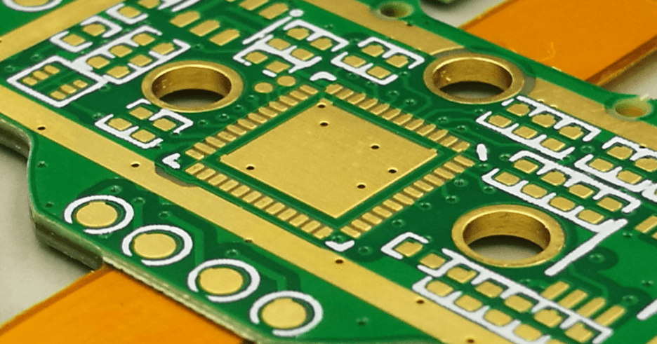
When referring to printed circuit boards, “rigid” means the board cannot get bent or twisted in any way. In comparison to other types of PCBs, the hard substrate offers this one extra strength. Once it’s made, there’s no going back on it.
The components of rigid printed circuit boards are rigid substrate, silkscreen coating, mask, and copper. Adhesives and heat are used to bond the layers together. This makes them possibly single- or double-sided. Multilayer or single-layer boards may also get used.
Some computers also use other rigid boards, but the motherboard is by far the most popular. This crucial part ensures that everything can talk to one another. It also moves data around, including the graphics processing unit, random access memory, and central processing unit.
Rigid PCB, as opposed to flexible PCB, is usable only in locations where the PCB must have a consistent shape over the lifetime of the device. Whether it’s a double, single, or multiple-layer board, they can all get used for the same sorts of things.
Noteworthy Characteristics of Rigid PCB
The stiff-printed circuit board (PCB) has a number of distinguishing features. To begin, the copper tracks and vias of a rigid PCB are all conveniently located on a single board. All the elements on the board get linked together via these traces.
A further distinguishing feature of the rigid boards is, as predictable from the name, the board’s solid substrate. That’s why it’s called a “stiff” substrate; it prevents the board from warping or bending. As an added bonus, this makes the board far more durable than flex PCB.
Once the manufacturer has manufactured these, no changes are possible because they are PCBs. This is why stiff boards can save you money and are more efficient than flexible boards.
Rigid boards are a vital component of computers, and while they have their limits, they should not get disregarded entirely. This is due to the fact that they are fundamental to any working computer. The motherboard is an instance of this.
How to manufacture Rigid PCBs?
Glues and heat are used to bond the various layers of rigid PCBs together. Because of this, the board has a sturdy, well-defined form. The completed board consists of multiple layers. The layers begin with the substrate and progress upward through the silkscreen, soldering mask, and copper.
1. Substrate Layer
When making stiff PCB, the first layer is the substrate. FR4 fiberglass is commonly used to construct this layer. The board’s rigidity is a result of the FR4 material, hence the name.
Phenolics and epoxies are two other potential materials for the substrate layer. These, however, are not as sturdy as FR4. Yet, their lower cost makes them attractive to some factories.
2. Copper Layer
A copper layer sits atop the substrate layer. Copper foil gets adhered to the substrate using heat and adhesives during manufacturing. Further, the copper layer facilitates information transfer via all available channels.
Double-sided boards coated with copper are used in high-end electronics. Furthermore, single-layered boards are used in less expensive devices, which may limit their usefulness.
3. Solder Mask Layer
When producing electronics, companies would typically cover the copper layers with a soldering mask layer for added protection of the copper tracks. Because of the insulation provided by the solder mask, the copper layer gets protected from damage that could get caused by contact with a conducting material.
4. Silkscreen Layer
The silkscreen layer comes last. To aid in comprehension, this layer places characters at the forefront of the board. Silkscreening these letters in a variety of colors is possible; white is just one of them.
Top Tips While Designing Rigid PCB
There are several factors to keep in mind while building a stiff circuit board. First, you need to think about the size of the board. Once printed, these panels are permanent and are not adjustable. Thus precise measurements are required. Now, whenever possible, build the board in a 3D printing program to ensure precision.
The board’s printing materials should get considered next. Copper is preferable for impedance control and carrying current, making it an essential material. However, designers need to understand the factors that affect which materials work best.
Careful calculations are required because the base can get constructed from epoxies, phenolics, and FR4 fiberglass. The fabricator can then choose the optimal material based on the results of the calculations.
What is the Difference Between Rigid & Flex PCB?
Flex and rigid PCBs are both used in electronics, although they get built and used very differently.
Rigid boards, as the name suggests, are rigid circuit boards that don’t bend or flex over time. Therefore, after the printing of the board, no changes are possible.
However, flex PCBs are bendable PCBs that can get shaped to meet a specific application. For this reason, these boards are more space-efficient than their inflexible counterparts. On the other hand, flex boards are often single-sided, as opposed to double-sided rigid PCB.
The higher production cost of flexible PCBs compared to rigid boards limits their usefulness in several applications. Despite being more expensive, they offer advantages than rigid that justify the additional expense. They’re not only adaptable but also superior at linking various circuits, electronic parts, and the GUI together. They are more flexible than their stiff counterparts, and they are lighter and better at dampening vibrations. Due to their malleability, they are less prone to distortion.
Major Applications of Rigid PCB
Rigid PCBs are widely used in a variety of electronic products due to their versatility. Among these are:
- Application as mainboards for desktop and portable computers
- Media for storing files and documents
- A component of mobile phones and other hand-held electronics
- In x-ray, pacemaker, and CT scan applications.
- Used in vehicles
- Used for boosting mobile phone signals and positioning devices
Examples of Rigid PCB Applications
Below are a few examples of where stiff PCBs find usefulness.
· Automation & Industrial Electronics
Rigid printed circuit boards get employed for both light and heavy load tasks. For regulated impedance and buried connections, multilayer PCBs are the way to go. Heavy-duty boards are useful for high-voltage and high-frequency uses. Robots, gas/pressure regulators, pick-and-place machines, surge suppressors, and so on are all forms of automation and control systems.
· Medical
While flexible PCBs are more common in the medical industry, stiff PCBs are equally useful. Most commonly, they get employed for massive, stationary machinery. Imaging technologies include things like MRI machines, EMG devices, and tomography scanners.
· Aerospace
Extreme conditions and high temperatures are typical in this business. Stiff PCBs can be useful in this situation since they can get made using large-temperature laminations and aluminum or copper substrates. APUs, cockpit instruments, temperature sensors, power converters, and control tower monitoring are all instances of aerospace industries.
· Automotive
Rigid printed circuit boards are used in automobiles of medium to large size. The printed circuit boards can be built on high aluminum and copper substrates, just like those used in aerospace industries. To counteract the effects of the engine’s heat and outside pollutants, high-temperature laminations can get installed. The use of plated copper in the fabrication of automotive PCBs increases their longevity. Power supply inverters, electronic control units, transmitting sensors, and distribution panels are just some of the many places rigid printed circuit boards (PCBs) find employment.
Major Types of RIGID PCB TYPES
Rigid printed circuit boards (PCBs) are useful because they are adaptable to meet the needs of a wide range of projects. Wide varieties of rigid PCBs are available from MCL.
· Single Sided:
The first printed circuit boards were single-sided. All the elements get concentrated on one part of the board, and there is only one conducting layer. Single-sided printed boards are advantageous because of their simplicity, which allows for rapid production with less room for error during assembly. This economical setup works best in low-density layouts.
· Double Sided:
Copper conducting layers are used on both sides of a double-sided PCB rather than just one. With double the area for elements, more design freedom, and the ability to implement more complicated circuitry, double-sided circuits can be used for a wide variety of applications.
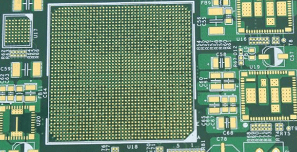
· Multilayered:
Multilayered PCBs have three or more conducting material layers in the center and several more layers around the core. Multilayered boards eliminate the need for wiring between components, conserve valuable real estate, and produce a robust and sturdy PCB thanks to their many layers and sophisticated curing process.
· Mechanical spacer or Carrier Board
Mechanical spacers or carrier boards are sometimes used in place of conducting layers on PCBs when a rigid backer gets required to support the boards during assembly. A circuit board’s copper layers and electrical connections are unnecessary for mechanical tasks.
Consideration Of Materials For Rigid PCB
Your rigid PCB components will get chosen in accordance with your project’s needs. Designing a stiff PCB is possible with a wide range of available materials.
CONDUCTOR
At MCL, we provide printed circuit boards with metal cores like aluminum, which provide good thermal conductivity at a reasonable price. We will utilize a metal core of your choosing; however, this will get tailored to your conductivity requirements.
ADHESIVES
Adhesive requirements are subject to change dependent on project specifics and conductor diameter. Options include:
- Acrylic
- Prepreg
- Epoxy
INSULATORS
We will supply a highly effective and secure insulator for your signal propagation needs. Among the potential resources are the following:
- Layers of solder mask, coverlay, and cover coat.
- Common FR-4 components.
- FR-4 materials that are not affected by the presence of lead.
In order to achieve higher stiffness and fire resistance, the majority of rigid PCBs, known as FR-4 circuit boards, get constructed with a layer of flame-retarding fiberglass. These boards are a great option for many uses because of their low weight and resistance to heat and moisture.
High-Tg boards find usage in situations when PCBs will get subjected to temperatures in excess of 150 °C. The heat created by high-power circuitry density configurations may be too much for the heat sinks and traces on a regular printed circuit board. In such cases, high-Tg circuits are the best option.
FINISHES
You’ll need to prevent oxidation and corrosion of the copper layer used in your stiff PCB so that electricity can flow efficiently. Some examples of possible protective coatings are:
- Immersion of electroless nickel-gold plating (ENIG).
- Immersion in palladium, gold, and nickel, all without electrolysis
- To get submerged in the tin.
- Precision leveling with hot air for soldering (HASL).
- Pure silver for immersion.
- High-strength, low-lead HASL.
- Electrolytic gold that can be wire bonded.
- Gold-fingered twang.
What are Rigid, Rigid-Flex, & Flex PCBs?
Let’s describe each kind of PCB before we get into the specifics of how they vary.
· Rigid PCBs
When you come across the word “PCB,” what you think is a rigid Printed Circuit Board. The board used in these parts is rigid and glass-reinforced, typically appearing green in color.
· Rigid-flex PCBs
A hybrid of flex and rigid PCBs is known as a rigid-flex PCB. The circuit substrates and PCB materials used to make these boards can be either flexible or rigid.
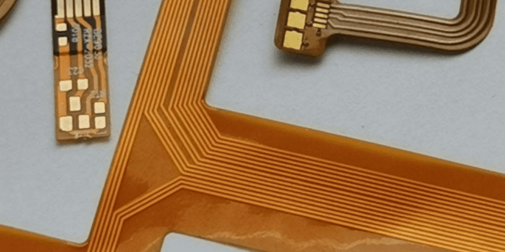
· Flex PCBs
Flexible printed circuit boards, or “flex PCBs,” are characterized by their malleable undersides. Flexible printed circuit boards (PCBs) are gaining popularity in modern electronics due to their resilience against vibration, adaptability to a variety of geometries, and efficient heat dissipation.
All electronic devices have a printed circuit board (PCB) at their core. PCBs are constructible with conducting lines on a non-conducting substrate.
Differences in Conductive Material
Different types of conducting materials are used to create flex, flex-rigid, and rigid PCBs. Printed circuit boards that are too rigid to bend, for instance, get fabricated from electro-deposited metal. But flexible printed circuit boards can get bent because the copper gets annealed.
Fabrication Differences
It stands to reason that several fabrication methods are applicable for flex-rigid, flex, and rigid printed circuit boards. Due to the nature of their construction, flexible PCBs must have the uncovered circuits of their components protected during the overlaying process. Conversely, rigid PCBs get made with the standard green solder mask.
Differences in Cost
Due to their flexibility and resistance to environmental variables, flexible PCBs are more costly to produce than rigid PCBs. However, because of its malleability, the device’s total area might potentially get lowered, resulting in further cost savings for the companies. In contrast, rigid PCBs can get made for far less money while still serving effectively in a wide variety of electrical contexts.
Differences in Applications
The flexibility of flex PCBs gives producers the freedom to tailor the board to each individual product. Rigid PCBs necessitate custom modifications to the device. Flex PCBs excel in applications such as healthcare electronics, wearable’s, and unmanned aerial vehicles. However, rigid PCBs find their best home in electronics and automobiles.
Comments are closed