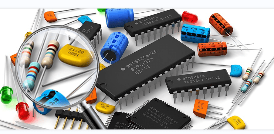
A circuit board is an integral part of any electronic device, from a simple calculator to a complex computer. It is a thin board made of insulating material that houses various electronic components, including resistors, capacitors, diodes, and transistors. These components work together to perform a specific function in the device.
Each component in a circuit board plays a crucial role in the overall functionality of the device. Resistors limit the flow of current, capacitors store electrical charge, diodes allow current to flow in one direction, and transistors act as electronic switches. Understanding the function of each component is essential in designing and troubleshooting electronic devices. In this article, we will take a closer look at the different components found in a circuit board and their roles in electronic devices.
Overview of Circuit Boards
What is a Circuit Board?
A circuit board, also known as a printed circuit board (PCB), is a thin board made of insulating material, such as fiberglass or plastic, with conductive pathways etched onto its surface. These pathways, called traces, are used to connect electronic components, such as resistors, capacitors, and transistors, to form a functioning circuit.
Circuit boards are essential components in modern electronics, from smartphones and laptops to cars and airplanes. They are used to control and regulate the flow of electricity in electronic devices, making them more efficient and reliable.
Types of Circuit Boards
There are several types of circuit boards, each designed for a specific purpose. Some of the most common types include:
- Single-sided PCBs: These have components and traces on only one side of the board.
- Double-sided PCBs: These have components and traces on both sides of the board, connected by vias (small holes) drilled through the board.
- Multi-layer PCBs: These have several layers of conductive material and insulating material sandwiched together, allowing for more complex circuits.
- Flexible PCBs: These are made of flexible materials, such as polyimide, and can be bent or folded to fit into tight spaces.
- Rigid-flex PCBs: These combine the flexibility of a flexible PCB with the rigidity of a rigid PCB, making them ideal for complex, three-dimensional designs.
Overall, circuit boards play a critical role in the functioning of modern electronics, and their design and construction continue to evolve to meet the demands of new technologies.
Components in Circuit Boards
Circuit boards are made up of different components that work together to perform specific functions. These components can be broadly categorized into three types: active components, passive components, and electromechanical components.
Active Components
Active components are electronic components that can control the flow of electricity. They require a source of power to operate and can amplify, switch, or generate electrical signals. Examples of active components include transistors, diodes, and integrated circuits.
Passive Components
Passive components, on the other hand, do not require a source of power to operate. They are designed to store, filter, or resist electrical signals. Examples of passive components include resistors, capacitors, and inductors.
Electromechanical Components
Electromechanical components are components that use both electrical and mechanical principles to perform their functions. They are designed to convert electrical energy into mechanical energy or vice versa. Examples of electromechanical components include relays, switches, and motors.
In summary, the components in circuit boards are essential for the proper functioning of electronic devices. Understanding the different types of components and their functions is crucial for designing and troubleshooting electronic circuits.
Designing Circuit Boards
Schematic Design
Schematic design is the first step in designing a circuit board. It involves creating a graphical representation of the circuit, showing the components and how they are connected. The schematic design is typically created using specialized software, such as Eagle or Altium Designer.
When designing the schematic, it is important to ensure that all components are correctly connected and that the circuit will function as intended. This requires a good understanding of the circuit’s purpose and the components being used.
Layout Design
Once the schematic design is complete, the next step is to create the layout design. This involves placing the components on the board and routing the connections between them. The layout design is also created using specialized software.
When designing the layout, it is important to consider the physical constraints of the board, such as the size and shape, as well as the electrical constraints, such as the impedance of the traces. It is also important to ensure that the board is easy to manufacture and assemble.
Conclusion
Designing circuit boards requires a good understanding of both the electrical and physical aspects of the circuit. By following the proper design process, including schematic design and layout design, it is possible to create a circuit board that functions as intended and is easy to manufacture and assemble.
Manufacturing Circuit Boards
Printed Circuit Board Fabrication
Printed circuit board (PCB) fabrication is the process of creating a custom-designed circuit board for electronic devices. The process involves several steps, including designing the circuit board layout, drilling holes, applying a copper layer, etching away excess copper, and applying a solder mask and silkscreen.
The first step in PCB fabrication is designing the circuit board layout using computer-aided design (CAD) software. Once the layout is finalized, the design is printed onto a special film that is used to transfer the design onto the copper layer of the board.
Next, the board is drilled to create holes for components and wiring. After drilling, a copper layer is applied to the board using a process called electroplating. The excess copper is then etched away using a chemical solution, leaving behind the desired circuit pattern.
Finally, a solder mask is applied to the board to protect the copper traces and prevent solder from flowing where it’s not intended. A silkscreen is also applied to label components and provide other information about the board.
Assembly
Once the PCB has been fabricated, it’s ready for assembly. This involves soldering components onto the board, which can be done by hand or using automated equipment.
The first step in assembly is to place the components onto the board in their designated locations. This is typically done using a pick-and-place machine, which can quickly and accurately place components onto the board.
Next, the board is sent through a soldering machine, which melts the solder and attaches the components to the board. This process can be done using wave soldering or reflow soldering, depending on the type of components being used.
After soldering, the board is inspected for defects and tested to ensure that it’s functioning properly. Any defects are repaired, and the board is ready to be integrated into an electronic device.
Overall, PCB fabrication and assembly are complex processes that require specialized knowledge and equipment. However, with the right tools and expertise, it’s possible to create high-quality circuit boards that meet the needs of a wide range of electronic devices.
Testing Circuit Boards
Functional Testing
Functional testing is the most common way to test circuit boards. It involves testing the board’s functions to ensure that they work as intended. This type of testing is done after the board has been assembled and all the components are in place.
To perform functional testing, the board is connected to a test fixture that simulates the conditions under which the board will be used. The test fixture sends signals to the board, and the board responds by performing its functions. The results of the test are recorded, and any defects are identified.
In-Circuit Testing

In-circuit testing is a more thorough way to test circuit boards. It involves testing the board’s components while they are still in place on the board. This type of testing is done before the board is assembled.
To perform in-circuit testing, a special test fixture is used that allows the tester to access the individual components on the board. The tester sends signals to each component and measures the response. This type of testing can identify defects that may not be found during functional testing.
In conclusion, both functional testing and in-circuit testing are important ways to test circuit boards. Functional testing is the most common way to test circuit boards, while in-circuit testing is a more thorough way to test the board’s components.
Comments are closed