The basis of all electrical gadgets has remained the PCBA board assembly. Without all these boards, all these devices just wouldn’t exist. Also, electronics are ubiquitous in our everyday lives. Circuit boards are used in all types of devices. A pcb is the tiny green board located in such devices.
However, there is a difference between a Circuit board and a PCBA. PCB is an empty board without no electronic components, whereas a PCBA is indeed a PCB including several electrical components. The boards are required for the production of electrical devices.
What is PCBA Circuit Board Assembly?
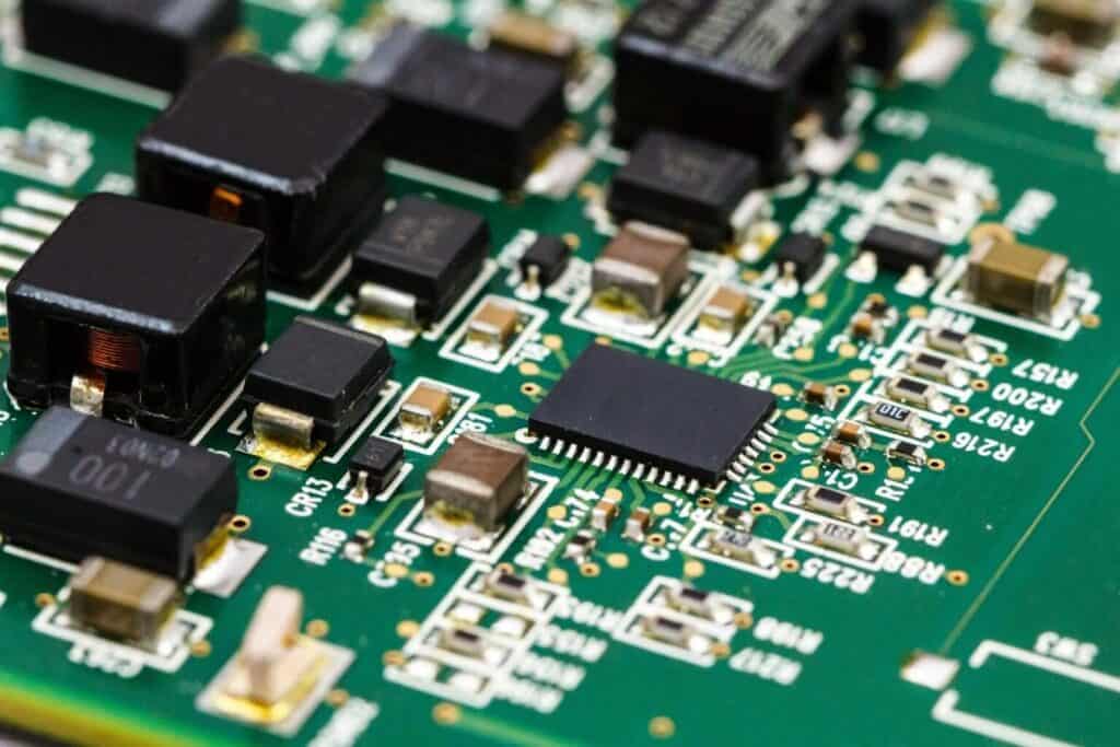
A PCBA assembly refers to a board in which electronics are mounted in order to create the finished product. The process of assembling electronics on the bare board is known as “PCBA.” Without these crucial components, there would be nothing for the bare circuit board to do.
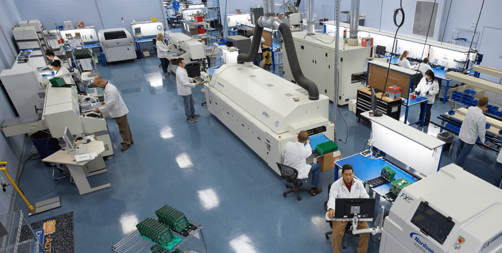
PCBA circuit board assembly is an important step in manufacturing an electronic component before it’s sent to the customer. In order to produce a PCBA, components have to be placed on an empty circuit board and soldered. Generally, manual or mechanical placement of the components is available for this process.

Make your own electronic device without a PCB board? Impossible! Besides this, conductive pathways are combined with a nonconductive material to form this assembly. You place electronic components where and when necessary to create the fully functional device. The process that creates these devices is called PCB assembly.
PCB Assembly is the process of connecting components in creating an object that functions properly. The assembly requires appropriate technology in order to be successful. In PCB assembly, there are two types of technology: Surface mount or SMT and Through hole or THT.
PCB assembly is not the same as PCB manufacturing. You’ll also need to plan out the design, layout and other components that go into creating your PCB board prototype.
Technologies for PCB Assembly
Surface mounting Technology
This SMT is a technique for attaching electronic components to a PCB. It entails using automated machines to place electronic components on the PCB surface. An automated process is integrated into surface mount. As a result, it is faster than the THT. This PCBA circuit board assembly technology does not require board drilling. It merely selects and positions electronic component on the PCB surface.
Additionally, SMT is known as an automated and flexible process that allows for greater connection densities. Furthermore, this process of assembly allows assemblers to help place the complex circuits into extremely small components.
Using through hole technology
The THT is known as a method that involves drilling holes in the circuit board. THT also aids in the formation of greater connections between the components. THT can be either fully or semi automated. This PCBA circuit board assembly technology also entails the insertion of components via holes.
Because this PCBA circuit board assembly is old, it is appropriate for some scenarios. This technology also makes it simple to connect the PCB details to the circuit’s inner layers.
The through- hole technology serves mechanically stressed components. Additionally, this PCBA circuit board assembly is best for prototyping and testing.
Mixed Technology
For mixed, it employs a hybrid of surface mount and through-hole technologies. Technology’s constant advancement has led to a demand for compact and more complex boards. Also, some PCBs include both SMD and the thru hole components.
SMT Vs THT: What’s the Difference?
Greater pin count
A distinction between the SMT and the THT is the number of pins. THT has fewer pins than SMT. Using leads in PCBs have been phased out as technology advances.
The technical cost
The thru hole technology helps in drilling holes in the board. The holes aid in the secure attachment of components. Drilling holes, on the other hand, takes time. The time and cost required to drill holes both adds to the THT’s technical cost. Because a machine aids in the completion of the SMT process, it takes less time.
Automation
In contrast to THT technology, the surface mount process is entirely automated. This process also involves the using different automated machines.
Placing the component
Through hole technology is used in place of surface mount technology for a few reasons. For one thing, through holes offer a stronger bond and require a hole to be drilled first before any parts are inserted.
Some common differences in component insertion exist–one being THT, which involves inserting components with leads into pre-drilled holes on a PCB, and the other being SMT, which is where components are attached to the surface of a PCB.
Soldering procedure
Here, the solder is melted by heated plates in a reflow-soldering process, sometimes called wave soldering. When the circuit board comes out of the oven, it is cooled and its surface is coated with molten solder.
Process of SMT Assembly
Several steps are involved in the PCB assembly.
Stenciling with solder paste
The application of solder paste is your first ever step when doing a PCB assembly. This step, however, is only works with SMT. THT does not require the using solder paste. The solder paste is applied by the assembler to the areas where these components should be.
Component placement
The assembler places these components of a surface mount directly on your PCB surface after applying the solder paste. This step necessitates using pick & place machines. The assembler in THT places the components by hand. This usually necessitates great care. SMT entails the incorporation of the robotic machine.
The Reflow Soldering
The board is passed through the oven in this step. Here, the oven goes ahead to heat the solder which then turns it liquid, ensuring a strong connection in-between the components. The PCB is then run via a cooler. This cooler aid in the solidification of a molten form of solder paste. This solder paste has to be solid in order for the components to remain in one place.
Inspection
The inspection aids in the detection of any board flaws. Inspection entails testing the circuit board’s functionality. These flaws are caused by the board movement in your reflow oven. Other flaws, such as misplaced components, could also exist.
Final inspection and Functional tests
Final inspection and functional tests are performed as the last step during SMT assembly. Functional tests aid in determining the board’s functionality. Furthermore, these tests simulate the circuit board’s normal operation. Power signals must pass the printed circuit board when the test is on, while the testers will examine the circuit’s electrical characteristics.
What is the Process of THT Assembly
Creating holes
Drilling of holes in a PCB is required for this. Furthermore, these holes have a variety of specifications. A drill file is a document that specifies the size and the hole’s location.
Lead positioning
This step entails inserting leads into drilled holes. Thru hole components should feature long leads. Next, attach the components of the thru hole and ensure that the lead is properly positioned in the holes in line with the design specifications. This can be done automatically or manually by the assembler.
Manual soldering vs. wave soldering
Instead of soldering paste, thru hole components use different methods of soldering. Wave soldering and manual soldering are the two soldering methods. Manual soldering involves the process of inserting a single component into a plated thru hole.
Furthermore, wave soldering is a distinct process. The board is soldered using a automated process. The board is placed on the conveyor belt by the assembler. This belt is heated in an oven. The molten solder flows over the bottom of the PCB in this oven. Then solder all of the pins present on the PCB’s bottom. For two-sided boards, wave soldering is fine.
Cleaning and inspection
Here, PCB assembly is inspected during this process to ensure that it functions properly. It is critical to remove any particles or debris that have accumulated on the circuit board.
PCBA Circuit Board Assembly Difficulties and Ways of Avoiding Them
During the PCB assembly process, PCB assemblers encounter some challenges and failures and challenges. It is critical to understand the failures as well as ways of avoiding them. Preventing some problems during PCB assembly can make the process more enjoyable for you.
Solder joint fracture
This can occur due to thermal coefficients of a board. In addition, if exposed to high temperatures, this issue can cause a PCB to fail. Manual soldering is a different cause of solder joint fracture. Integrating automatic equipment for soldering the electrical parts on a board is one method of preventing fracture of the solder joint. Apply the right amount of the solder paste to the board as well.
Short Circuits
This is quite common during the PCB assembly. High current solder bridges, spikes, or moisture could lead to short circuits. Furthermore, this issue has the potential to damage the entire PCB. Also, you can avoid this by visually inspecting the PCB surface for hanging parts. Furthermore, electrical testing may be required to detect open or short circuits early.
De-wetting
When electronic components fail, de-wetting may occur. When solder joints de-wetted, they become loose. De-wetting is caused by overheating, contamination, and corrosion. A thorough board inspection could aid in the detection of this issue.
PCB bending or cracking
During the PCBA process, a circuit board could crack or bend. Circuit boards typically cracks or bends due to mechanical and physical stress. Pre-baking and storing the printed circuit board in places that are humidity controlled is the best way to avoid bends and cracks.
What is the Cost of PCB Assembly?
The PCB assembly cost has to do with some factors. Furthermore, the cost of PCB assembly can range from $5 to hundred dollars. The price range involves these factors below.
PCB complexity
The complex boards frequently necessitate a time-consuming assembly process. Complex boards, such as high-density interconnections, rigid-flex, as well as boards of high frequency, take longer to assemble. Additionally, if this circuit needs drilling, the cost of PCB assembly will be higher.
Methods of assembly
The cost of PCB assembly is determined by the type of assembly technology used. Because SMT requires using automated machines, it is less expensive than THT. The process of the THT assembly takes longer because holes on your PCB must be drilled.
Customization
This will increase the PCB assembly cost. Also, if you request custom PCBs, be prepared to spend more. It will happen because the PCB assembler may spend more just to meet all your requirements.
Time to complete
If you request that your circuit board be delivered quickly, you will most probably spend more for PCB assembly. It will happen because the PCB assembler will have to cancel some orders just to meet your deadline. They may even have to work overnight at times to meet the deadline.
Layers
More layers equal more money and time. A multilayer PCBA circuit board assembly, for example, will cost more to assemble than the assembly of a one layer PCB.
Labor expenses
The cost of labor varies by region. Labor may influence the PCB assembly cost.
PCBA Circuit Board Assembly Process Design Considerations
When it comes to PCBA circuit board assembly, you must make critical decisions. This decision includes the method of component placement and the type of soldering. The best decision will maximize efficiency.
Component choice
In terms of the schematic, the assembler chooses components with specific values. The mounting technology is then selected. Additionally, PCB designers must adhere to some guidelines when selecting components.
Select more SMT components and only THT components if SMT versions are unavailable. Also, if the PCB design allows, use a similar package type.
Soldering technique
Choosing the appropriate soldering technique is critical for your PCBA process. Furthermore, the soldering technique should be suitable for the components to be soldered. Reflow soldering isn’t ideal when THT components are present. Only THT components in the assembly benefit from wave soldering. Manual soldering is ideal only when selective or wave soldering methods cannot be used to solder THT components.
Component positioning
Components can be placed manually or automatically. Ensure proper component spacing and part orientation during component placement.
Conclusion
It is recommended that printed circuit board assembly be done with care, attention to detail, and absolute precision, because this will determine the efficient functioning of the electronic devices.
Comments are closed