Circuit boards are an essential component of modern electronics, serving as the foundation for everything from smartphones to satellites. These small, flat boards are made up of a complex network of conductive pathways that allow electricity to flow between components.
The process of creating a circuit board involves several steps, including designing the layout, choosing the appropriate materials, and etching the board itself. The design process typically involves the use of computer-aided design (CAD) software, which allows engineers to create a digital representation of the board and test its functionality before it is physically produced.
Once the design is finalized, the board is typically manufactured using a combination of automated and manual processes. This may involve drilling holes for components, applying a layer of copper to the board, and using chemical processes to remove excess copper and create the necessary pathways. The end result is a high-quality circuit board that is capable of powering a wide range of electronic devices.
The Basics of Circuit Board Manufacturing
Designing the Circuit Board
The first step in circuit board manufacturing is designing the board. This involves creating a schematic of the circuit and laying out the components on the board. The design process also includes selecting the appropriate materials and determining the size and shape of the board.
Creating the Printed Circuit Board (PCB)
Once the design is complete, the next step is to create the printed circuit board (PCB). This involves transferring the design onto a copper-clad board using a process called photolithography. The board is then etched to remove the unwanted copper and create the circuit traces.
After the etching process, the board is cleaned and drilled to create holes for the components. The holes are plated with metal to create electrical connections between the different layers of the board.
Adding Components to the PCB
The final step in circuit board manufacturing is adding the components to the PCB. This involves soldering the components onto the board using a soldering iron or a reflow oven.
It is important to ensure that the components are placed correctly and that the solder joints are strong and reliable. Once the components are in place, the board is tested to ensure that it functions correctly.
Overall, circuit board manufacturing is a complex process that requires careful attention to detail and a thorough understanding of electronics. By following the proper design and manufacturing processes, it is possible to create high-quality circuit boards that meet the needs of a wide range of applications.
Types of Circuit Boards
Circuit boards are essential components of electronic devices, and they come in various types. The three most common types of circuit boards are single-sided, double-sided, and multi-layer circuit boards.
Single-Sided Circuit Boards
Single-sided circuit boards are the simplest type of circuit boards. They have a single layer of conductive material, usually copper, on one side of the board. The other side of the board is blank, with no conductive material. Single-sided circuit boards are commonly used in simple electronic devices such as calculators, remote controls, and toys.
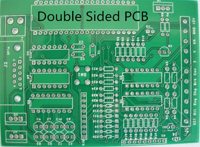
Double-Sided Circuit Boards
Double-sided circuit boards have conductive material on both sides of the board. The conductive material on each side is connected by holes drilled through the board. Double-sided circuit boards are more complex than single-sided circuit boards and are commonly used in more complex electronic devices such as computers, printers, and audio equipment.
Multi-Layer Circuit Boards
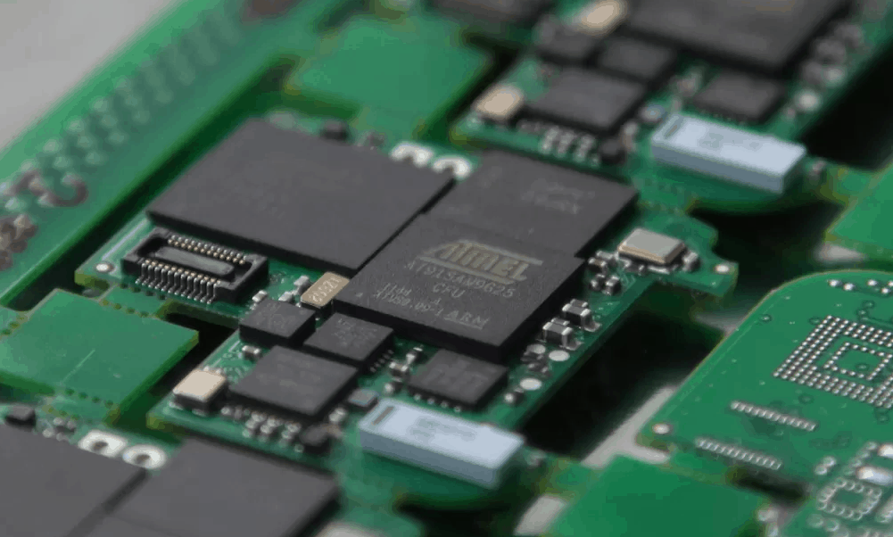
Multi-layer circuit boards have multiple layers of conductive material separated by insulating layers. The layers are connected by drilled holes, and the conductive material is etched to create the circuitry. Multi-layer circuit boards are the most complex type of circuit boards and are commonly used in high-performance electronic devices such as smartphones, tablets, and medical equipment.
In summary, the type of circuit board used in an electronic device depends on the complexity of the device and its performance requirements. Single-sided circuit boards are suitable for simple devices, while double-sided and multi-layer circuit boards are necessary for more complex devices.
Materials Used in Circuit Board Manufacturing
Copper
Copper is the most common metal used in circuit board manufacturing due to its excellent electrical conductivity and corrosion resistance. Copper is used to create the conductive traces that carry electrical signals between components on the board. The thickness of the copper layer can vary depending on the specific application and requirements of the circuit board.
Substrates
The substrate is the base material on which the circuit board is built. The most common substrate materials used in circuit board manufacturing are fiberglass-reinforced epoxy resin, also known as FR-4, and polyimide. FR-4 is a rigid substrate that is widely used in most circuit board applications, while polyimide is a flexible substrate that is used in applications where flexibility is required, such as in medical devices or aerospace applications.
Solder Mask
Solder mask is a protective layer applied to the circuit board to protect the copper traces from oxidation and to prevent solder from flowing where it is not intended. Solder mask is typically made of a liquid photoimageable polymer that is applied to the board and then cured with UV light. The most common colors for solder mask are green, red, and blue.
In addition to copper, substrates, and solder mask, there are other materials used in circuit board manufacturing, such as solder paste, which is used to attach components to the board, and silkscreen, which is used to add text and graphics to the board. Overall, the selection of materials used in circuit board manufacturing is critical to the performance and reliability of the final product.
Manufacturing Processes for Circuit Boards
Circuit boards are a crucial component of electronic devices. They are used to connect electronic components and provide the necessary power and signal connections. Circuit boards are manufactured using various techniques, including Through-Hole Technology, Surface-Mount Technology (SMT), and Mixed Technology.
Through-Hole Technology
Through-Hole Technology is the oldest method of circuit board manufacturing. It involves drilling holes through the board and inserting components through the holes. The components are then soldered to the board using a wave soldering process. Through-Hole Technology is still used today for some applications, such as high-power circuits.
Surface-Mount Technology (SMT)
Surface-Mount Technology (SMT) is a newer method of circuit board manufacturing. It involves placing components directly onto the surface of the board and soldering them in place using a reflow soldering process. SMT components are smaller and lighter than Through-Hole components, making them ideal for smaller devices. SMT is the most common method of circuit board manufacturing today.
Mixed Technology
Mixed Technology is a combination of Through-Hole and SMT methods. It involves using both Through-Hole and SMT components on the same board. Mixed Technology is used when Through-Hole components are required for high-power circuits, and SMT components are required for smaller, lighter circuits.
In conclusion, circuit board manufacturing processes have evolved over the years, with Through-Hole Technology being the oldest, SMT being the most common, and Mixed Technology being used when both Through-Hole and SMT components are required.
Quality Control in Circuit Board Manufacturing
Quality control is a crucial part of circuit board manufacturing. It ensures that the end product meets the required standards and specifications. In this section, we will discuss the different aspects of quality control in circuit board manufacturing.
Incoming Inspection
Incoming inspection is the first step in quality control. It involves checking the materials and components that are received from suppliers. The inspection includes checking the dimensions, tolerances, and specifications of the materials and components. Any non-conforming materials or components are rejected, and the supplier is informed.
In-Process Inspection
In-process inspection is done during the manufacturing process. It involves checking the quality of the circuit board at various stages of production. The inspection includes checking the dimensions, tolerances, and specifications of the circuit board. Any defects or non-conformities are corrected, and the process is repeated until the desired quality is achieved.
Final Inspection
Final inspection is done once the circuit board is complete. It involves checking the quality of the finished product. The inspection includes checking the dimensions, tolerances, and specifications of the circuit board. Any defects or non-conformities are corrected, and the circuit board is approved for shipment.
Testing
Testing is an essential part of quality control in circuit board manufacturing. It involves verifying that the circuit board performs as expected. The testing includes functional testing, electrical testing, and environmental testing. Any issues found during testing are corrected, and the circuit board is retested until it meets the required standards and specifications.
In conclusion, quality control is a critical aspect of circuit board manufacturing. It ensures that the end product meets the required standards and specifications. By following the above quality control steps, manufacturers can produce high-quality circuit boards that meet the needs of their customers.
Future of Circuit Board Manufacturing
As technology continues to evolve, circuit board manufacturing is also expected to undergo significant changes in the future. Here are some potential developments that could shape the future of circuit board manufacturing:
-
Flexible Circuit Boards: Flexible circuit boards, also known as flex circuits, are gaining popularity due to their ability to bend and twist without breaking. They are ideal for use in wearable technology, medical devices, and other applications where flexibility is essential. In the future, we can expect to see more flexible circuit boards being developed, which could lead to new and innovative products.
-
3D Printing: 3D printing technology has the potential to revolutionize circuit board manufacturing by allowing for the creation of complex circuit board designs that would be difficult or impossible to produce using traditional manufacturing methods. As 3D printing technology continues to improve, we can expect to see more circuit boards being produced using this method.
-
Artificial Intelligence: Artificial intelligence (AI) has the potential to streamline the circuit board manufacturing process by optimizing production, reducing waste, and improving quality control. AI can analyze data from sensors and other sources to identify potential issues before they become major problems, allowing for faster and more efficient troubleshooting.
-
Internet of Things: The Internet of Things (IoT) is a network of interconnected devices that communicate with each other to perform various tasks. In the future, we can expect to see more circuit boards being developed specifically for IoT applications. These circuit boards will need to be smaller, more energy-efficient, and capable of communicating with other devices wirelessly.
In conclusion, the future of circuit board manufacturing looks promising, with new technologies and innovations on the horizon. As these technologies continue to evolve, we can expect to see faster, more efficient, and more reliable circuit board production.
Comments are closed