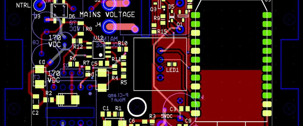
Circuit boards are an essential component of modern-day electronics. They are the backbone of all electronic devices, from smartphones to computers to automobiles. Circuit boards are made up of various materials, each with its own unique properties and benefits. One of the most commonly used materials in circuit board manufacturing is fiberglass.
Fiberglass is a type of reinforced plastic that is made up of glass fibers embedded in a resin matrix. It is an ideal material for circuit board manufacturing because of its high strength, durability, and resistance to heat and moisture. Fiberglass circuit boards are also lightweight and easy to work with, making them a popular choice for manufacturers.
Another popular material used in circuit board manufacturing is ceramic. Ceramic circuit boards are made up of a mixture of ceramic powder and a binder, which is then molded and fired at high temperatures. Ceramic circuit boards are known for their high thermal conductivity, which makes them ideal for use in high-temperature applications. They are also highly resistant to wear and tear, making them a popular choice for industrial and military applications.
Materials Used in Circuit Board Manufacturing
Substrates
The substrate is the base material that supports the conductive layers of a circuit board. Common substrate materials include:
- FR4: A fiberglass-reinforced epoxy laminate that is widely used due to its low cost and good electrical insulation properties.
- Polyimide: A high-temperature plastic that is used in applications where the board will be exposed to extreme temperatures.
- Rogers: A high-frequency substrate that is used in applications where signal integrity is critical.
Conductors
Conductors are the metal traces that carry electrical signals between components on a circuit board. The most commonly used conductor material is copper, which is applied to the substrate using a process called etching.
Solder Mask
The solder mask is a protective layer that covers the conductive traces on a circuit board. It prevents solder from flowing onto areas where it is not needed and protects the board from environmental damage. Solder mask materials include epoxy, polyurethane, and acrylic.
Surface Finish
The surface finish is the final coating applied to the surface of a circuit board. It is used to protect the board from oxidation and to ensure that components can be easily soldered onto the board. Common surface finish materials include:
- HASL: Hot Air Solder Leveling is a process that applies a layer of molten solder to the board and then levels it using hot air.
- ENIG: Electroless Nickel Immersion Gold is a process that applies a layer of nickel to the board, followed by a layer of gold.
- OSP: Organic Solderability Preservatives is a process that applies a thin layer of organic material to the board to protect it from oxidation.
Plating
Plating is the process of applying a thin layer of metal to the surface of a circuit board. This is done to improve the conductivity of the board and to protect it from environmental damage. Common plating materials include:
- Gold: A highly conductive metal that is used in applications where signal integrity is critical.
- Tin: A low-cost plating material that is widely used in consumer electronics.
- Nickel: A durable plating material that is used in applications where the board will be exposed to hrsh environmental conditions.
Types of Circuit Boards
There are three main types of circuit boards: single-sided, double-sided, and multi-layer. Each type has its own advantages and disadvantages, and is used for different applications.
Single-Sided Circuit Boards
Single-sided circuit boards are the simplest and most basic type of circuit board. They consist of a single layer of copper on one side of an insulating material, usually fiberglass. The components are mounted on the copper side, and the connections between them are made by etching away the copper to create the desired circuit pattern.
Single-sided circuit boards are cheap and easy to manufacture, but they have limited functionality and are not suitable for complex circuits.
Double-Sided Circuit Boards
Double-sided circuit boards have copper on both sides of the insulating material. The components are mounted on both sides, and the connections between them are made by drilling holes through the board and plating them with copper to create a conductive path between the two sides.
Double-sided circuit boards are more versatile than single-sided boards, and can be used for more complex circuits. They are also more expensive to manufacture.
Multi-Layer Circuit Boards
Multi-layer circuit boards consist of multiple layers of copper and insulating material, with vias connecting the layers. The components are mounted on the top and bottom layers, and the connections between them are made by the vias.
Multi-layer circuit boards are used for very complex circuits, and can have dozens of layers. They are more expensive to manufacture than single-sided or double-sided boards, but they offer more functionality and better performance.
In summary, the type of circuit board used depends on the complexity of the circuit and the budget available. Single-sided boards are suitable for simple circuits, while double-sided and multi-layer boards are used for more complex circuits.

Circuit Board Fabrication Process
Designing the Circuit Board
The first step in the circuit board fabrication process is to design the circuit board using computer-aided design (CAD) software. The design should include all the necessary components, such as resistors, capacitors, and transistors, as well as the necessary connections between them. The software can also perform a design rule check to ensure that the design meets the required specifications.
Printing the Circuit Board
Once the design is complete, the next step is to print it onto a copper-clad board using a printer that is capable of printing the design onto the board. The printer uses a special ink that is resistant to the etching process.
Etching the Circuit Board
The next step is to etch the board, which involves removing the unwanted copper from the board using a chemical process. The board is immersed in an etching solution that dissolves the copper, leaving behind only the copper that is part of the circuit design.
Drilling Holes
After the board has been etched, the next step is to drill holes in the board for the components. The holes are drilled using a computer-controlled drilling machine that ensures that the holes are in the correct location and of the correct size.
Plating and Coating the Circuit Board
The final step in the circuit board fabrication process is to plate and coat the board to protect it from corrosion and to ensure that the components are securely attached. The board is first plated with a thin layer of copper to improve its conductivity, and then coated with a layer of solder mask to protect it from corrosion. Finally, the board is coated with a layer of silkscreen to label the components and provide additional protection.
In conclusion, the circuit board fabrication process is a complex process that requires careful attention to detail and the use of specialized equipment. By following the steps outlined in this section, it is possible to create a high-quality circuit board that meets the required specifications.
Testing and Quality Control
Visual Inspection
Before a circuit board is tested, it undergoes a visual inspection to ensure it meets certain quality standards. The board is inspected for any visible defects, such as scratches, cracks, or discoloration. The inspector also checks for proper labeling and markings, as well as the correct orientation of components. Any issues found during this inspection are noted and addressed before further testing.

Electrical Testing
Electrical testing is an important step in ensuring the circuit board functions properly. This testing involves checking the board for continuity, shorts, and opens using a multimeter. The board is also checked for proper voltage and resistance levels. Any issues found during this testing are noted and addressed before further testing.
Functional Testing
Functional testing is the final step in testing a circuit board. This testing involves powering up the board and checking its functionality. The board is tested for proper signal flow, timing, and response to inputs. Any issues found during this testing are noted and addressed before the board is approved for use.
Overall, testing and quality control are critical steps in the production of a circuit board. By ensuring that each board meets certain quality standards, manufacturers can be confident that their products will function properly and reliably.
Conclusion
In conclusion, materials used in circuit boards play a crucial role in the performance and reliability of the electronic devices they power. The choice of materials depends on various factors such as the application, operating conditions, and cost.
From our analysis, we can conclude that FR-4 is the most commonly used material for manufacturing circuit boards due to its low cost and excellent electrical properties. However, for high-frequency applications, materials such as Rogers 4350B and Taconic RF-35 are preferred due to their low dielectric loss and high thermal stability.
Furthermore, it is essential to note that the choice of materials affects the manufacturing process, and the overall cost of the circuit board. Therefore, manufacturers must carefully consider the trade-offs between performance, cost, and reliability when selecting materials for their circuit boards.
In summary, the selection of materials for circuit boards is a critical decision that impacts the performance, reliability, and cost of electronic devices. Manufacturers must consider various factors when selecting materials for their circuit boards to ensure optimal performance and reliability.
Comments are closed