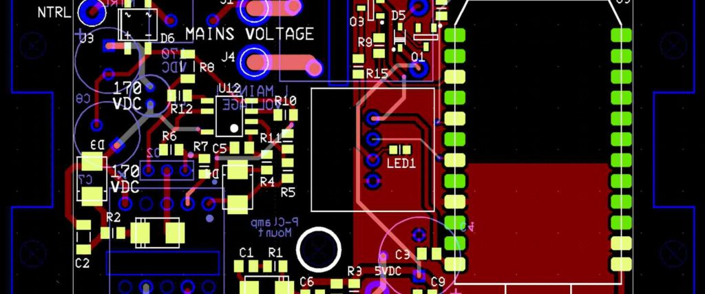
Multi-layer PCB assembly is a complex process that involves the integration of multiple layers of printed circuit boards. This technology is used in a wide range of industries, including aerospace, automotive, and consumer electronics. Multi-layer PCBs offer numerous advantages over traditional single-layer PCBs, including increased functionality and reduced size.
One of the primary benefits of multi-layer PCB assembly is the ability to integrate more components into a smaller space. This is particularly important in industries like aerospace and automotive, where space is at a premium. Multi-layer PCBs also offer improved performance and reliability, as they are less prone to interference and can better withstand harsh environmental conditions.
Overall, multi-layer PCB assembly is a critical technology for a wide range of industries. As the demand for smaller, more powerful electronic devices continues to grow, the importance of multi-layer PCBs is only likely to increase.
Overview of Multi Layer PCB Assembly
What is Multi Layer PCB Assembly?
Multi Layer PCB Assembly refers to the process of assembling printed circuit boards that have multiple layers of conductive material. These layers are separated by insulating material, and each layer is connected to the other layers through plated through-holes. Multi Layer PCB Assembly is used in a wide range of electronic devices, including smartphones, computers, and medical equipment.
Why is Multi Layer PCB Assembly Important?
Multi Layer PCB Assembly is important because it allows electronic devices to be more compact and efficient. By using multiple layers of conductive material, more components can be placed on a single board, reducing the size of the device. Additionally, the use of plated through-holes allows for better connectivity between the layers, improving the overall performance of the device.
Benefits of Multi Layer PCB Assembly
There are several benefits to using Multi Layer PCB Assembly. These include:
-
Increased density of components: Multi Layer PCB Assembly allows for a higher density of components to be placed on a single board, reducing the size of the device.
-
Improved performance: The use of plated through-holes allows for better connectivity between the layers, improving the overall performance of the device.
-
Better reliability: Multi Layer PCB Assembly is more reliable than single layer PCBs, as the use of multiple layers and plated through-holes reduces the risk of connectivity issues.
-
Reduced interference: By separating the layers with insulating material, Multi Layer PCB Assembly reduces the risk of interference between components.
Overall, Multi Layer PCB Assembly is an important process in the manufacturing of electronic devices, allowing for increased efficiency, reliability, and performance.
Designing Multi Layer PCB Assembly
When designing a multi-layer PCB assembly, there are several factors to consider to ensure optimal performance and functionality.

Factors to Consider
Firstly, the number of layers required for the PCB assembly should be determined based on the complexity of the circuit and the space available. Additionally, the thickness of the PCB, the type of materials used, and the routing of the traces should also be taken into account.
Another important factor to consider is the heat dissipation of the PCB assembly. Adequate thermal management is crucial for preventing overheating and ensuring the longevity of the components.
Types of Multi Layer PCB Assembly Designs
There are several types of multi-layer PCB assembly designs, including:
- Stackup design: This involves layering the PCBs in a specific order to achieve the desired functionality.
- Blind and buried vias: These are used to connect layers of the PCB that are not adjacent to each other.
- Microvia technology: This involves creating small holes in the PCB to allow for more compact designs.
The choice of design will depend on the specific requirements of the project.
Tools and Software for Designing Multi Layer PCB Assembly
Several tools and software are available for designing multi-layer PCB assemblies, including:
- Altium Designer
- Eagle PCB Design
- KiCAD
- OrCAD
- PADS
These tools offer a range of features, such as schematic capture, PCB layout, and 3D visualization, to help streamline the design process and ensure accuracy.
In conclusion, designing a multi-layer PCB assembly requires careful consideration of various factors, the selection of an appropriate design, and the use of reliable tools and software.
Manufacturing Multi Layer PCB Assembly
Step-by-Step Process of Manufacturing Multi Layer PCB Assembly
The manufacturing process of multi-layer PCB assembly involves several steps. The following are the steps involved in the process:
-
Designing the PCB: The first step involves designing the PCB using software such as Eagle, Altium, or KiCAD. The design includes the layout of the components, the routing of the traces, and the number of layers required.
-
Printing the Inner Layers: The second step involves printing the inner layers of the PCB. The inner layers are printed on a copper-clad board using a photoresist process.
-
Drilling and Plating: The third step involves drilling the holes and plating them with copper. This process is done to create the vias and through-holes required for the components to connect.
-
Lamination and Bonding: The fourth step involves laminating the layers together and bonding them using heat and pressure. This process creates a multi-layer PCB.
-
Solder Mask and Silk Screen: The fifth step involves applying a solder mask and silk screen to the PCB. The solder mask is applied to prevent solder from flowing where it is not intended, and the silk screen is applied to label the components.
-
Testing and Inspection: The final step involves testing and inspecting the PCB to ensure that it meets the required specifications.
Materials and Equipment Required
The following are the materials and equipment required for manufacturing multi-layer PCB assembly:
- Copper-clad board
- Photoresist
- Copper plating solution
- Lamination press
- Solder mask and silk screen ink
- PCB drilling machine
- Soldering iron
- Multimeter
- Oscilloscope
- X-ray machine
Quality Control Measures
To ensure the quality of the multi-layer PCB assembly, the following measures are taken:
- Visual inspection of the PCB
- Electrical testing of the PCB
- X-ray inspection of the PCB
- IPC-A-600 standard compliance
The above measures ensure that the PCB meets the required specifications and is free from defects.
In conclusion, the manufacturing of multi-layer PCB assembly involves several steps, materials, and equipment. Quality control measures are taken to ensure that the PCB meets the required specifications and is free from defects.
Testing Multi Layer PCB Assembly
Types of Tests
Before delivering a multi-layer PCB assembly to the customer, it is essential to perform various tests to ensure that the PCB assembly is working correctly. There are different types of tests that can be performed on a multi-layer PCB assembly, including:
-
Visual Inspection: This test is performed to ensure that the assembly has been built correctly and that all components are placed in their respective positions.
-
Electrical Tests: These tests are performed to ensure that the PCB assembly is functioning correctly. This test includes testing for continuity, shorts, and open circuits.
-
Functional Tests: These tests are performed to ensure that the PCB assembly meets the customer’s specifications. This test involves testing the PCB assembly’s functionality, such as power consumption, signal quality, and temperature.

Testing Methods
There are different methods for testing multi-layer PCB assemblies, including:
-
Automated Optical Inspection (AOI): This method uses cameras and image recognition software to detect defects in the PCB assembly.
-
In-Circuit Testing (ICT): This method uses a bed-of-nails fixture to test the electrical connectivity of the PCB assembly.
-
Flying Probe Testing: This method uses a flying probe to test the electrical connectivity of the PCB assembly.
Common Issues and How to Address Them
There are several common issues that can occur during the testing of multi-layer PCB assemblies, including:
-
Shorts: Shorts can occur due to component placement errors or manufacturing defects. To address this issue, the PCB assembly should be inspected, and the shorted components should be replaced.
-
Opens: Opens can occur due to soldering defects or component placement errors. To address this issue, the PCB assembly should be inspected, and the open connections should be repaired.
-
Insufficient Solder: Insufficient solder can occur due to various reasons, such as incorrect solder paste application or incorrect reflow profile. To address this issue, the PCB assembly should be inspected, and the insufficiently soldered components should be reworked.
In conclusion, testing multi-layer PCB assemblies is a crucial step in ensuring that the PCB assembly is functioning correctly. By performing various tests and using different testing methods, common issues can be identified and addressed, ensuring that the PCB assembly meets the customer’s specifications.
Applications of Multi Layer PCB Assembly
Multi-layer PCB assembly is a popular choice for a wide range of applications due to its ability to provide more complex circuit designs in a compact form factor. Here are some of the most common applications of multi-layer PCB assembly:
Consumer Electronics
Multi-layer PCB assembly is widely used in consumer electronics products, such as smartphones, tablets, laptops, and gaming consoles. These devices require complex circuit designs that can fit into a small form factor while providing high performance. Multi-layer PCBs enable manufacturers to achieve this by stacking multiple layers of circuitry on top of each other, reducing the overall size of the board.
Industrial Automation
Multi-layer PCB assembly is also widely used in industrial automation systems, such as robotics, control systems, and manufacturing equipment. These systems require high reliability and performance, and multi-layer PCBs can provide the necessary circuit density to meet these requirements. Additionally, multi-layer PCBs can help reduce the overall size of the system, making it more compact and efficient.
Medical Devices
Multi-layer PCB assembly is commonly used in medical devices, such as imaging equipment, patient monitoring systems, and diagnostic tools. These devices require high accuracy, reliability, and performance, and multi-layer PCBs can help achieve these requirements. Additionally, multi-layer PCBs can provide the necessary circuit density to fit the complex circuitry required in these devices into a small form factor.
In summary, multi-layer PCB assembly is a popular choice for a wide range of applications due to its ability to provide complex circuit designs in a compact form factor. Consumer electronics, industrial automation, and medical devices are just a few of the many applications that can benefit from multi-layer PCB assembly.
Comments are closed