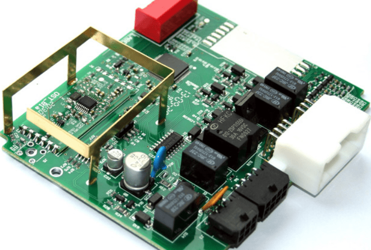
Printed circuit boards (PCBs) are an essential part of modern electronics. They are used in a wide range of devices, from smartphones and laptops to medical equipment and industrial machinery. A PCB is a board made of insulating material, such as fiberglass or plastic, with conductive pathways etched onto its surface. These pathways allow electrical signals to flow between the components mounted on the board.
One type of PCB that has gained popularity in recent years is the printed circuit board stator. A stator is a key component of an electric motor, and it is responsible for generating the magnetic field that interacts with the rotor to produce rotational motion. Traditional stators are made of laminated steel sheets, but PCB stators offer several advantages over their steel counterparts. They are lighter, more efficient, and easier to manufacture, making them ideal for applications where weight and size are critical factors.
Overview of Printed Circuit Board Stator
What is a Printed Circuit Board Stator?
A Printed Circuit Board (PCB) Stator is an innovative technology that is used in electric motors. It is a type of stator that is made up of a printed circuit board instead of traditional wire windings. The PCB stator is made up of multiple layers of copper tracks, which are etched onto a substrate. The tracks are arranged in a specific pattern to create the magnetic field that drives the motor.
How does a Printed Circuit Board Stator work?
The PCB stator works by generating a magnetic field that interacts with the rotor to produce motion. When an electric current flows through the copper tracks on the stator, it creates a magnetic field. This magnetic field interacts with the magnetic field of the rotor, which causes the rotor to rotate. The PCB stator is designed to maximize the magnetic field strength while minimizing losses due to heat and other factors.
One of the key benefits of the PCB stator is that it is more efficient than traditional wire windings. The copper tracks on the PCB stator are thinner than wire windings, which reduces the resistance and losses in the system. This leads to a more efficient motor, which can save energy and reduce costs.
In addition, the PCB stator is more compact than traditional wire windings. The copper tracks can be arranged in a more complex pattern, which allows for a higher density of magnetic field lines. This results in a more powerful motor that can produce more torque and operate at higher speeds.
Overall, the PCB stator is a promising technology that has the potential to revolutionize the electric motor industry. Its efficiency, compactness, and power make it an attractive option for a wide range of applications.
Advantages of Printed Circuit Board Stator
Cost-effective manufacturing process
One of the biggest advantages of printed circuit board (PCB) stator is its cost-effective manufacturing process. PCB stator is manufactured using a highly automated process that reduces the overall cost of production. The automated process also ensures that the PCB stator is manufactured with high precision and accuracy, which reduces the chances of defects and errors.
Reduced size and weight
Another advantage of PCB stator is its reduced size and weight. The use of PCB technology allows for a more compact design, which reduces the overall size and weight of the stator. This is particularly useful in applications where space is limited or weight is a concern, such as in aerospace or automotive industries.
Improved reliability and durability
PCB stator also offers improved reliability and durability compared to traditional stators. The use of PCB technology allows for a more robust design, which can withstand harsh environments and vibrations. Additionally, the use of high-quality materials and advanced manufacturing processes ensures that PCB stator is built to last.
In summary, PCB stator offers several advantages over traditional stators, including cost-effective manufacturing process, reduced size and weight, and improved reliability and durability. These advantages make PCB stator an ideal choice for a wide range of applications, from aerospace to automotive industries.
Applications of Printed Circuit Board Stator
Electric Motors
Printed Circuit Board (PCB) stators are used in electric motors to provide a more efficient and reliable alternative to traditional copper wire windings. PCB stators can be designed to have a higher slot fill factor, which means that more copper can be placed in the same space, resulting in a higher power density. Additionally, PCB stators can be designed to have a more uniform magnetic field, resulting in less energy loss and higher efficiency. These benefits make PCB stators an attractive option for electric vehicles, robotics, and other applications where high efficiency and power density are critical.
Generators
PCB stators can also be used in generators to improve efficiency and reduce size and weight. Like in electric motors, PCB stators can be designed to have a higher slot fill factor and a more uniform magnetic field, resulting in higher efficiency and power density. Additionally, PCB stators can be designed to have a lower profile than traditional copper wire windings, which can reduce the overall size and weight of the generator.
Transformers
PCB stators can also be used in transformers to improve efficiency and reduce size and weight. PCB stators can be designed to have a higher slot fill factor and a more uniform magnetic field, resulting in higher efficiency and power density. Additionally, PCB stators can be designed to have a lower profile than traditional copper wire windings, which can reduce the overall size and weight of the transformer.
In summary, PCB stators offer a range of benefits over traditional copper wire windings in electric motors, generators, and transformers. These benefits include higher efficiency, higher power density, and reduced size and weight. As a result, PCB stators are becoming an increasingly popular choice for a range of applications where efficiency and power density are critical.
Design and Fabrication of Printed Circuit Board Stator
Design Considerations
The design of a printed circuit board stator involves several considerations to ensure optimal performance. Some of the key design considerations include the number of poles, the size of the stator, the shape of the stator, and the thickness of the copper traces. The number of poles determines the speed and torque of the motor, while the size and shape of the stator affect the efficiency and power output. The thickness of the copper traces affects the current-carrying capacity and the resistance of the stator.
Manufacturing Process
The manufacturing process of a printed circuit board stator involves several steps, including designing the circuit board, printing the circuit board, etching the copper traces, drilling holes, and assembling the stator. The design of the circuit board is created using computer-aided design (CAD) software, which generates a digital file that is used to print the circuit board. The printed circuit board is then etched to remove the unwanted copper and leave behind the traces that form the stator.
After etching, the circuit board is drilled to create holes for the motor shaft and other components. The stator is then assembled by inserting the components into the holes and soldering them in place. The final step is to test the stator to ensure that it meets the required specifications.
In conclusion, the design and fabrication of a printed circuit board stator involves several considerations and steps that must be carefully planned and executed to ensure optimal performance. By following the proper design and manufacturing processes, a high-quality printed circuit board stator can be produced that meets the needs of various motor applications.
Challenges and Limitations of Printed Circuit Board Stator

Limited Power Handling Capacity
One of the main challenges with printed circuit board (PCB) stator is its limited power handling capacity. Due to the nature of PCBs, they are not able to handle high power levels, making them unsuitable for high-performance applications. This is because PCBs have a limited ability to dissipate heat, which can lead to overheating and failure of the stator.
Limited Flexibility in Design
Another limitation of PCB stator is its limited flexibility in design. Unlike traditional wire-wound stators, PCB stators have a fixed design, which makes them less adaptable to different applications. This can limit their usefulness in certain industries, such as aerospace or automotive, where flexibility in design is essential.
In addition, PCB stators are typically more expensive to manufacture than wire-wound stators, which can limit their adoption in certain industries where cost is a major consideration.
Despite these limitations, PCB stators have several advantages over traditional wire-wound stators, including increased efficiency, reduced size and weight, and improved reliability. As such, they are becoming increasingly popular in a variety of industries, including robotics, medical devices, and consumer electronics.
Comments are closed