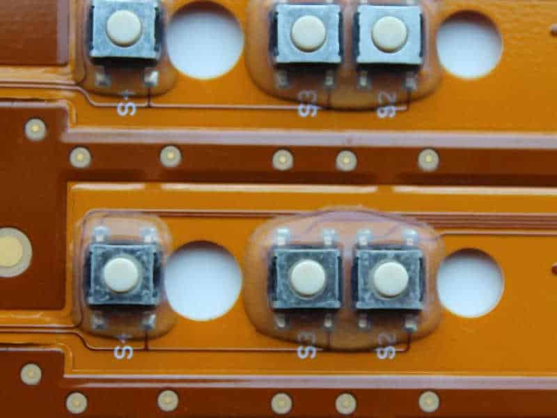
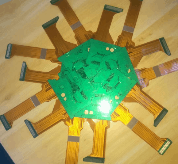
Flex circuit PCBs, also known as flexible printed circuit boards, are a type of electronic circuit board that can be bent, folded, and twisted to fit into tight spaces or unusual shapes. They are made up of a thin layer of flexible material, typically polyimide or polyester, with conductive traces etched onto the surface. These traces allow for the transfer of electrical signals and power between components.
Flex circuit PCBs have become increasingly popular in recent years due to their ability to reduce the size and weight of electronic devices. They are commonly used in applications such as smartphones, wearables, medical devices, and automotive electronics. In addition to their flexibility, they offer other benefits such as improved reliability, reduced assembly time, and increased design flexibility. However, they also present unique challenges in terms of manufacturing and testing, which require specialized equipment and expertise.
What is a Flex Circuit PCB?
Definition of Flex Circuit PCB
A Flex Circuit PCB, also known as a Flexible Printed Circuit Board, is a type of electronic circuit board that is designed to be flexible and bendable. It is made up of a thin, flexible substrate material, typically made of polyimide or polyester film, and features conductive traces and components that are etched onto the surface of the substrate.
Advantages of Flex Circuit PCBs
Flex Circuit PCBs offer several advantages over traditional rigid circuit boards. They are lightweight, thin, and flexible, which makes them ideal for use in applications where space is limited. They also offer excellent resistance to vibration and shock, making them well-suited for use in harsh environments. In addition, Flex Circuit PCBs can be designed to fit into complex shapes and contours, which makes them ideal for use in products that require a high degree of customization.
Applications of Flex Circuit PCBs
Flex Circuit PCBs are used in a wide range of applications, including medical devices, aerospace and defense systems, consumer electronics, and automotive electronics. In the medical field, Flex Circuit PCBs are used in devices such as pacemakers, defibrillators, and insulin pumps. In the aerospace and defense industries, they are used in navigation systems, communication systems, and missile guidance systems. In the consumer electronics industry, they are used in smartphones, tablets, and wearable devices. And in the automotive industry, they are used in sensors, lighting systems, and entertainment systems.
Overall, Flex Circuit PCBs offer a number of advantages over traditional rigid circuit boards, making them an attractive option for a wide range of applications.
Design and Manufacturing
Design Considerations
Designing a flex circuit PCB requires careful consideration of several factors. The design must be optimized for the intended use, taking into account the required size, shape, and electrical properties. Some key design considerations include:
- Flexibility: The flexibility of the circuit is a critical factor in determining the design. The circuit must be able to bend and flex without breaking or losing electrical connectivity.
- Stackup: The stackup of the circuit is also important. The number of layers and their arrangement can affect the performance of the circuit.
- Trace Width and Spacing: The width and spacing of the traces must be carefully chosen to ensure proper electrical performance and reliability.
- Connector Placement: The placement of connectors on the circuit board is crucial. The connectors must be placed in a location that allows for easy connection and disconnection without damaging the circuit.
Manufacturing Process

The manufacturing process for flex circuit PCBs is different from that of traditional PCBs. The process involves several steps, including:
- Preparation: The first step in the manufacturing process is to prepare the substrate. The substrate is typically made of a flexible material, such as polyimide or polyester.
- Etching: The next step is to etch the circuit pattern onto the substrate. This is done using a chemical etching process.
- Drilling: After the circuit pattern has been etched onto the substrate, holes are drilled for the components and connectors.
- Plating: The next step is to plate the circuit with a conductive material, typically copper. This is done to improve the electrical conductivity of the circuit.
- Lamination: Once the circuit has been plated, it is laminated with a coverlay material. The coverlay provides insulation and protection for the circuit.
- Testing: The final step in the manufacturing process is to test the circuit for electrical performance and reliability.
In conclusion, designing and manufacturing flex circuit PCBs requires careful consideration of several factors. The design must be optimized for the intended use, taking into account the required size, shape, and electrical properties. The manufacturing process is also different from that of traditional PCBs, involving several steps, including preparation, etching, drilling, plating, lamination, and testing.
Materials Used in Flex Circuit PCBs
Flex circuit PCBs are made up of several materials that work together to create a flexible and reliable circuit. In this section, we will discuss the three main types of materials used in flex circuit PCBs: substrate materials, conductive materials, and insulating materials.
Substrate Materials
The substrate material is the backbone of the flex circuit PCB. It provides the physical support for the circuit and is responsible for maintaining its shape. Some of the most common substrate materials used in flex circuit PCBs include:
- Polyimide (PI): This is the most commonly used substrate material for flex circuit PCBs. It is known for its excellent mechanical properties, high-temperature resistance, and flexibility.
- Polyester (PET): PET is a low-cost and flexible substrate material that is commonly used in consumer electronics and other low-power applications.
- Liquid Crystal Polymer (LCP): LCP is a high-performance substrate material that is known for its low dielectric constant, high-temperature resistance, and excellent chemical resistance.
Conductive Materials
Conductive materials are used to create the electrical paths in the flex circuit PCB. They are responsible for carrying electrical signals from one point to another. Some of the most common conductive materials used in flex circuit PCBs include:
- Copper: Copper is the most commonly used conductive material in flex circuit PCBs. It is known for its excellent conductivity, low cost, and ease of use.
- Silver: Silver is a high-performance conductive material that is commonly used in high-frequency applications.
- Gold: Gold is a highly reliable conductive material that is commonly used in applications where high corrosion resistance is required.
Insulating Materials
Insulating materials are used to separate the conductive paths in the flex circuit PCB. They prevent electrical signals from interfering with each other and ensure that the circuit operates reliably. Some of the most common insulating materials used in flex circuit PCBs include:
- Polyimide (PI): PI is also commonly used as an insulating material in flex circuit PCBs. It is known for its excellent mechanical properties and high-temperature resistance.
- Epoxy: Epoxy is a low-cost insulating material that is commonly used in consumer electronics and other low-power applications.
- Acrylic: Acrylic is a high-performance insulating material that is known for its excellent chemical resistance and high-temperature resistance.
In conclusion, the materials used in flex circuit PCBs play a critical role in determining the performance, reliability, and flexibility of the circuit. By choosing the right combination of substrate, conductive, and insulating materials, designers can create circuits that meet the specific needs of their applications.
Types of Flex Circuit PCBs
Flex circuit PCBs come in different types depending on the number of layers they have. The three main types of flex circuit PCBs are:
Single Layer Flex Circuit PCBs
Single layer flex circuit PCBs are the simplest and most common type of flex circuit PCB. They consist of a single layer of flexible material with conductive traces on one side. Single layer flex circuit PCBs are ideal for applications that require a small number of connections and a high degree of flexibility. They are also cost-effective and easy to manufacture.
Double Layer Flex Circuit PCBs

Double layer flex circuit PCBs have two layers of flexible material with conductive traces on both sides. They are more complex than single layer flex circuit PCBs, but they offer more design flexibility and can accommodate a larger number of connections. Double layer flex circuit PCBs are commonly used in applications where space is limited, such as in medical devices and aerospace equipment.
Multi-Layer Flex Circuit PCBs
Multi-layer flex circuit PCBs have three or more layers of flexible material with conductive traces on both sides. They are the most complex type of flex circuit PCB and offer the highest level of design flexibility. Multi-layer flex circuit PCBs are commonly used in applications that require a large number of connections and a high degree of reliability, such as in automotive and telecommunications equipment.
In addition to the number of layers, flex circuit PCBs can also be classified based on their construction, such as single-sided, double-sided, and multi-layer. The choice of flex circuit PCB type depends on the specific requirements of the application, such as the number of connections, space limitations, and reliability.
Testing and Inspection
Testing Methods
Flex circuit PCBs require thorough testing to ensure they meet the necessary specifications and standards. There are various testing methods that can be used to ensure that the flex circuit PCB is functioning correctly. Some of the commonly used testing methods include:
- Continuity testing: This method checks if there are any breaks in the circuit by measuring the resistance between two points.
- Impedance testing: This method measures the resistance to the flow of electrical current in the circuit.
- Hi-Pot testing: This method tests the insulation of the circuit by applying a high voltage to it.
Quality Inspection
Quality inspection is an essential part of the manufacturing process for flex circuit PCBs. It ensures that the PCBs meet the required quality standards and specifications. Some of the quality inspection methods include:
- Visual inspection: This method involves examining the PCB for any visible defects such as scratches, dents, or other physical damage.
- X-ray inspection: This method is used to detect any hidden defects such as cracks or voids in the PCB.
- Microsection analysis: This method involves examining a cross-section of the PCB to check for any defects in the layers.
In conclusion, testing and inspection are critical aspects of the manufacturing process for flex circuit PCBs. Using the appropriate testing methods and quality inspection techniques ensures that the PCBs meet the required specifications and standards.
Future of Flex Circuit PCBs
Flex circuit PCBs have come a long way since their inception. Their thin and flexible nature has made them an ideal choice for various applications, including wearable devices, medical devices, and automotive electronics. With the advancements in technology, flex circuits are expected to become even more popular in the future.

One of the major trends in the future of flex circuit PCBs is the increasing demand for miniaturization. As electronic devices become smaller and more compact, the need for smaller and thinner PCBs also increases. Flex circuits are an excellent solution for this demand, as they can be made thinner and more flexible than traditional rigid PCBs.
Another trend is the growing demand for high-speed data transfer. Flex circuits can be designed to handle high-speed signals, making them an ideal choice for applications such as 5G networks and autonomous vehicles. With the increasing demand for high-speed data transfer, the demand for flex circuits is expected to grow significantly.
Flex circuits are also expected to become more environmentally friendly in the future. As companies strive to reduce their carbon footprint, they are looking for ways to make their products more sustainable. Flex circuits can be made using materials that are more eco-friendly than traditional rigid PCBs, making them an ideal choice for companies looking to reduce their environmental impact.
In conclusion, the future of flex circuit PCBs looks bright. With their thin and flexible nature, ability to handle high-speed signals, and potential for eco-friendliness, they are expected to become even more popular in the future.
Comments are closed