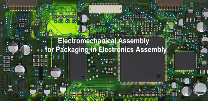
One of the essential aspects of the production and manufacturing of electronic devices is the interconnection between different device parts. In electronics assembly manufacturing, various ways to solve interconnection problems have been introduced. Electromechanical assembly deals with the interconnection and packaging of completed electronic assemblies. Some essential types of interconnections are listed below.
- On-the-Device: Discrete connections are created between the semiconductive parts of integrated circuits (ICs) in the form of tiny etched wires.
- Device-to-Package: The semiconductor die is enclosed in a specialized package connected to the package’s terminals with thin aluminum or gold wires.
- Package-to-Board: Flat, round, or square package terminals are connected to a PCB as permanent or separable connections.
- Board-to-Board: Permanent or separable connectors and cables connect circuit boards.
- On-Board: Components are interconnected with the conductive track of the circuit board.
- Board-to-Cabinet: Connections between a circuit board and its cabinet are made with separable connectors.
- Cabinet-to-Cabinet: Separable connections between cabinets are made with multiple contact cables.
From the perspective of the interconnection, many other random approaches are possible. In contrast, the above list provides a useful overview of the electrical assembly. Type 1, 2, and 3 deal with the manufacturers’ various methods to combine electronic components on a printed circuit board, using either through-hole or surface mounted components. The remaining Types deal with the interconnections such that fully assembled boards are connected, enclosed in cabinets, and made available to the customer.
————————————————————-
Request Electronic Contract Manufacturing Quote, Pls Send PCB File to Sales@raypcb.com Now
————————————————————-
Electromechanical Packaging
The packaging is a form of design that affects all stages of an appliance’s life and not just the interconnection. Good packaging design is beneficial for the device, the customer, and the manufacturer. Poor packaging design, on the other hand, is detrimental to all. Packaging processes and techniques used to house electronic assemblies have been standardized. Many metal and plastic cabinets are available off-the-shelf. Some aspects considered during electromechanical assembly are the selection of adhesives, dissipation of heat, environmental aspects, and electromagnetic interference.
Adhesives
Substances that stick things together are called adhesives. Glue is a popularly used name. There are many areas in electromechanical packaging where adhesives are used. Every application requires a specialized adhesive, and adhesives suitable for one adherend may not be suitable for the other. Adhesives perfectly matched in one type of joint may be unsuitable in another. Some adherends such as glass, polyethylene, polypropylene, PTFE, silicone are extremely difficult to bond. The following are the main types of adhesives.
Acrylics are the toughened form of adhesives, and they require a catalyst for curing. Anaerobics sealants are used for locking threaded parts, and their high viscosity variants can be used to form gaskets. Cyanoacrylate is super glue adhesives, and it hardens in a few seconds. Epoxide resins can be heat-cured, and they yield high performance. Finally, Polyurethanes show good performance with greater susceptibility to moisture.
Furthermore, adhesives are found in many forms and grades, such as emulsion, solution, powder, and stick. If two different adherends are to be used in a joint, make sure suggested adhesives are compatible. After the selection of as many adhesives as possible, tests should be performed to determine the ideal.
Heat Management
Today, circuit boards have extreme packing densities. The closer together components get, the warmer the assembly gets. Packing heat can lead to problems such as damage to components and variable reliability. The use of heat-sinks and similar natural techniques is known as passive heat management. Forced heat dissipation by cooling fans, etc., is called active heat management.
A liquid heat-sink (LHS) is a bag of fluid mounted between board or substrate and assembly’s metal housing. Heat is dissipated from the components by convection through the fluid to the housing to maintain a low temperature.
New active techniques have been developed to dissipate large amounts of heat, including heat exchange systems and refrigeration systems. Such drastic techniques are cumbersome and costly. Simple passive solutions have been recently developed to aid heat dissipation. They include thermal vias, thermal planes, and base materials with good thermal conductivity. Thermal vias are plated-through holes in the circuit board, underneath and around a component, and they dissipate heat away from the component through the copper track on either side of the board.
Most base materials in both through-hole and surface mounted assemblies are of epoxy-resin with a glass fiber reinforcement(Through-Hole Vs Surface Mount Assembly). The thermal resistance of such boards is high. Therefore, a solution to thermal problems can be to make circuit boards with low thermal resistance materials. The board effectively acts as a heat-sink, dissipating heat from components. Thermal planes are usually of copper or aluminum. Copper has the lowest thermal resistance.
A plane must conform to the circuit board, in that component terminations have to be made through the plane. Chemical milling, or CNC machining, is used to machine thermal planes to fit the board. The design of thermal planes is usually undertaken by computer-aided thermal path analysis. A single component is mounted on an epoxy-resin circuit board. The board is mounted in card guides, attached to a metal cabinet.
A thermal bridge above a component can channel heat from the top of the component down to the thermal plane. Thermal modules are particularly useful in surface mount assemblies where thermal planes cannot be placed underneath components. In such cases, heat dissipation may only be from above the component.
————————————————————-
Request Electronic Contract Manufacturing Quote, Pls Send PCB File to Sales@raypcb.com Now
————————————————————-
Environmental Aspects
The packaging design must be made, keeping in mind the environment in which the device is operated. Environments can have considerable effects on assemblies in domestic use. Customers subject their devices to an extreme environment. Handling and transportation even may cause damage to assemblies.
Environmental protection of cabinets and housings
In most instances, surfaces of cabinets and housings are protected by several methods against corrosion. Some improvements in a cabinet or housing surfaces are sought regarding resistance to wear, electrical insulation or conductivity, or thermal dissipation. Methods of protecting or improving surfaces are usually known as finishes.
Aluminum or aluminum alloy finishes
There are a large number of ways to finish aluminum or aluminum alloy surfaces. Anodizing, blackening, plating, and zinc spraying are all options. Alloys susceptible to corrosion may be sprayed with aluminum to protect them from corrosion. The coating may need to be regularly renewed in some cases, and anodized aluminum layers are electrically insulating.
Ferrous metal finishes
Generally, ferrous metals require corrosion protection finishes. Some stainless steels do not require finishing for corrosion protection purposes. The main finishes for ferrous metals are Galvanizing, that is, dipping the ferrous metal in molten zinc, and plating, generally of cadmium, chromium, or zinc.
Organic material finishes
Plastic and wood cabinets and housings are typically finished only to improve electrical conductivity. Primary methods of finishing include Cathodic sputtering, Conductive paints, Electroless plating, and metal spraying.
Environmental Protection Packaging
Electronic components assemblies, and devices can be subjected to extreme conditions such as corrosion or high mechanical activity. It is possible to reduce the influence of these extreme conditions to appropriate standards but cannot be eliminated entirely. Some useful methods of encapsulation are listed below.
Conformal coating
They shield against humidity, dirt, vaporous contaminants, and other foreign objects by creating an electrically insulating screen. Coting must be selected based on the environment of the device in which it will be used. Some coatings are not suitable for constantly damp environments, such as when condensation is met. Electrostatically sensitive parts can be affected by the application of a conformal coating by spraying, so manufacturers’ precautions should be followed. The most common conformal coating materials include acrylic, epoxy, polyurethane, and silicone. The conformal process of encapsulation is typically performed by brushing, dipping, flow coating, or spraying. The soldering process referred to as cushioning involves coating the circuit board with a thin plastic sheet to prevent it from being damaged during soldering.
Embedding
Shielding via embedding works by enveloping an assembly or an electronic component completely inside a protective substance. A mold is essential to restrict the encapsulating substance while curing. When the substance hardens, the assembly is taken out of the mold.
————————————————————-
Request Electronic Contract Manufacturing Quote, Pls Send PCB File to Sales@raypcb.com Now
————————————————————-
Impregnation and Potting
To provide environmental shielding, impregnation strategies focus on injecting content into all intermediate spaces or spacing between components. Potting is a technique of embedding where the enclosing substance binds to the mold or casing.
Encapsulation design considerations
Where embedded, potted, or impregnated encapsulation methods are used, assemblies generally cannot be repaired and must be considered disposable. Within limits, conformally coated assemblies can be repaired. Any material or process which causes damage in any way to an assembly is self-defeating. Curing resins may generate exothermic heat, which raises the local temperature above the maximum specified for specific heat-sensitive components. Certain resins under mechanical stresses such as vibration generate voltages that may be large enough to damage electrostatically sensitive components. Most encapsulation materials do not adhere to materials such as polyethylene and PTFE. There is little point in encapsulating an assembly to protect it against corrosion if contaminants in the form of flux or grease moisture are present. There are two areas of concern. First, a component’s effective thermal dissipation may be decreased by encapsulation, causing damage to the component. Second, dissipation from a component may be sufficient to damage the encapsulating material.
Electromagnetic Compatibility
Electrical appliances should be able to operate without causing electromagnetic interference (EMI). Some of the aspects of EMI are listed below.
Packaging Considerations
EMI is a human-made form of noise with a few notable exceptions. It usually is possible to devise ways of reducing its effects to an acceptable level. In theory, to formulate techniques to control EMI, we first need to understand what EMI is and how it arises. In practice, it is challenging to predict at the design stage. Only when the device is fully built can a measurement be taken, so any action can only be corrective, not preventive. Other causes of EMI include Radio transmitters, Non-radio high-frequency generators, Electrostatic discharge, Lightning, and Power line interference.
Reducing EMI by Screening
Primarily, the radiated EMI is avoided by using a box build metal casing, which is grounded. If the enclosure itself cannot be made up of metal, then an internal metal cage can be used to act as a screen. This screen would shield both the EMI source and EMI victim. The EMI absorption of steel casings is better than aluminum or copper if the thickness is greater than 1 mm. Similarly, if the thickness is less than one millimeter, then EMI absorption of aluminum and copper is the same. The best protection can be achieved using a metal enclosure with conductive gaskets to prevent small through-holes and use perforated grids to cover ventilation holes. The most effective form of shielding is a grounded screen.
A metal enclosure is unsuitable in most cases due to cost or aesthetics. Plastic and wood do not offer shielding from EMI; therefore, an internal screen is typically included. A metal acrylic sheet may be covered with plastic boxes at the development level, allowing adequate shielding and good appearance at a low cost. Aerosol sprays allow the user to incorporate a metalized conductive coating onto the inside of plastic enclosures providing EMI attenuation up to 50 db.
Cabling Techniques
In an enclosure or box build casing, one cable may induce noise into other cables. This effect is known as crosstalk EMI. Cables are ordered into three categories, such as power cables causing potential interference, DC control cables, and power supply cables causing electromagnetic interference, and Signal and logic cables, mostly victims but in some cases the source of interference. Three sets of cables must be routed in the enclosure as far apart from each other as room permits. Ensure that the signal and logic cables are routed at maximum possible distances from other groups.
Cables carrying low-level digital or analog signals are of three types containing ribbon cable, coaxial cable, and twisted pair. Any cable should have its return running next to it, thus reducing the signal loop region. The lengthier the cable, the greater the risk of interference. Coaxial cable has an electrostatic shield or screen; it works similarly to the metal box build or casing. The resistance of the screen with respect to the ground should be zero in order for it to work correctly. If there is a measurable resistance to the screen, the noise voltage between the screen and the true ground is generated by electromagnetic interference. The twisted-pair cable protects since the interference voltages are identical and cancel each other in each turn of the twisted wire pair.
Printed Circuit Board Techniques
Many techniques used in electromagnetic interference reduction in cable routing can also be adopted when designing circuit boards. Ground loops can occur in analog circuits where two or more amplifying stages are in series. On power supply printed circuit boards, ripple and high-frequency noise can be reduced if connections are made as large as possible, using copper planes rather than individual tracks. On signal boards, it is advisable to leave copper on any unused areas of the board. These can then be grounded to reduce ripple and noise levels. Another solution is to provide a common grounding point for all parts of the circuit. The guard ring approach may be useful for circuits that require a high impedance input.
Reducing EMI using Filters
Electromagnetic interference on AC supply and input power terminals is present in the form of voltage surges and transient currents. A filter at the equipment’s input can be installed to attenuate the disturbance and reduce EMI. Filters can also be equipped with low-level signal connectors. Transient spikes and surges on the AC power lead may reach peaks much higher than the equipment can cope with, and filters cannot dissipate the extra energy.
Comments are closed